Continue to Site

Welcome to EDAboard.com

Welcome to our site! EDAboard.com is an international Electronics Discussion Forum focused on EDA software, circuits, schematics, books, theory, papers, asic, pld, 8051, DSP, Network, RF, Analog Design, PCB, Service Manuals... and a whole lot more! To participate you need to register. Registration is free. Click here to register now.

uBlox GPS CAM-M8Q 3D-Fix Problem

Status
Not open for further replies.

sakibnaz

Full Member level 3
Full Member level 3
Joined
Jul 6, 2008
Messages
165
Helped
6
Reputation
12
Reaction score
6
Trophy points
1,298
Activity points
2,778
Hi.

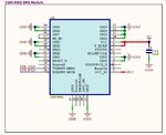
For my project I used uBlox CAM-M8Q. Attached is the schematic. Here V2-3.3v which is output of a LDO.

But when I am observing the GPS UART data I can see the 3D Fix not occurred. Below are the captured data:

> $GNVTG,,,,,,,,,N*2E
> $GNGGA,,,,,,0,00,99.99,,,,,,*56
> $GNGSA,A,1,,,,,,,,,,,,,99.99,99.99,99.99*2E
> $GPGSV,1,1,00*79
> $GLGSV,1,1,00*65
> $GNGLL,,,,,,V,N*7A
> $GNRMC,,V,,,,,,,,,,N*4D

I am using internal Chip antenna of the Module.

Can anyone advise me on my Schematic? Is the any initialization command needed to issue to make the 3D-Fix?

Thanks in advance.

Regards.
 

Attachments

  • CAM-M8Q_Schematic.jpg
    CAM-M8Q_Schematic.jpg
    58.9 KB · Views: 291

hi,
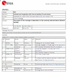
Your message > $GNGLL,,,,,,V,N*7A, displaying a 'V' in Field #6, which indicates Invalid data.

Look at this image from the uBlox Receiver Protocol Specification pdf.

How long did you keep the receiver powered ON.? it takes time to get a lock, especially indoors, say about 5 minutes depending upon the location.
E

EDIT:
Download from the web a copy of the Protocol pdf.
 

Attachments

  • AAesp01.gif
    AAesp01.gif
    51.3 KB · Views: 242
  • AAesp02.gif
    AAesp02.gif
    12.7 KB · Views: 227
Hi.

Thanks for reply.

Yes I know "V" indicates invalid signal i.e. no 3D-Fix. I tried to keep it under open sky for around 30 min ... but no luck :(

Is my Schematic is Ok?

I already checked the protocol Doc. And I think after power on Module should report Valid NMEA automatically after 3D-Fix.

Any advise?

Regards.
 
hi,
Your circuit looks OK to me.
Do you a copy of the receiver protocols.?
E
**broken link removed**
 
Hi Yes, I checked the M8 protocol. Do you used CAM-M8Q Module before ...?

Regards.
 
Hello,
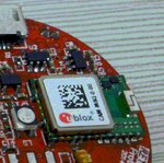
Which your antenna module uses? and how it was fixed? (post a picture)
I'm asking because, positioning may not be the right way to pick up the signal.;-)
 
Hi.

I am using CAM-M8Q Module. My PCB is round type and attached is a picture.

I am just afraid ... is my Schematic is Ok? And is there any initialization Command need to be send to make the 3D Fix?

Thanks in advance.

Regards.
 

Attachments

  • CAM_M8Q_PCB.JPG
    CAM_M8Q_PCB.JPG
    88.1 KB · Views: 245
hi,
I have written working programs for the uBlox NEO-6M unit, using the UART I/O.

The d/s for the CAM-M8Q indicates that the unit factory default configuration should output data messages.

Have you attempted to modify the defaults using the CFG-PRT commands.?

E
 

Attachments

  • AAesp01.gif
    AAesp01.gif
    24.5 KB · Views: 225
Hi.

I did not send any command to change the default settings. I just power on my Board and scan the GPS UART TXD Data.

Still no luck on 3D-Fix :(

Regards.
 
Hi All.

I am still in the problem.

One ques .... For CAM-M8Q Module its mentioned that, Pin ANT and Pin RF_IN needs to be connected using a Short Trace. But is this Short trace needs to be 50Ohm controlled? In my design I connected this two pins directly and did not consider 50Ohm Trace.

Please advise.

Regards.
 
Hi Did you have any success fixing this problem?

I have just begun to use this module and am having a similar issue.

Previously i have used the UC530 (which the CAM-M8Q replaces) with no need to configure any settings.
Also i had just joined the ANT and RF_IN pins directly together.

Regards,
Damian
 
Hi.

For my project I used uBlox CAM-M8Q. Attached is the schematic. Here V2-3.3v which is output of a LDO.

But when I am observing the GPS UART data I can see the 3D Fix not occurred. Below are the captured data:


I am using internal Chip antenna of the Module.

Can anyone advise me on my Schematic? Is the any initialization command needed to issue to make the 3D-Fix?

Thanks in advance.

Regards.

Hi, I am having the same issue on my board with the u-blox CAM-M8Q, always invalid data are coming from the gps module, have you found a way to solve the problem?

Thanks
Marco
 

Have anyone solve this problem?

I've got the same schematic as sakibnaz, I'm receiving frames via serial port, even I can communicate with M8Q with u-center (ublox software), but all the time GPS module doesn't get any useful data from satellites.

Best regards,

Kaza
 

I resolved the problem. On my PCB, I had GND polygon on the bottom layer directly under the antenna (the top layer had ground plane clearance). The GND under the antenna blocked signal and caused interference. Probably PCB designer forgot about ground plane clearance on that layer. The solution was to mill PCB - 5x8mm polygon - remove copper under the antenna.
For more information read the manual at page 14-15 - 2.6 PCB layout suggestion - (CAM-M8Q_HardwareIntegrationManual.pdf)

PROBLEM:
Module communicates via serial port and sends proper NMEA frames, but can't get GPS fix.

SOLUTION:
Check top and bottom PCB layer, whether directly under the antenna you've got plane clearance (5x8mm) through all layers.

TIPS:
- Also remember if you are using embedded antenna to go outside (inside building you're probably won't get fix).
- Before PCB design read the manual (there are also some useful information about CAM-M8Q placement).
- CAM-MQ8 should get fix and send proper data over the serial port with default configuration - just as it arrives from factory.

Hope this will help someone. :-D

Best regards,
 
Status
Not open for further replies.

Similar threads

Part and Inventory Search

Welcome to EDABoard.com

Sponsor

Back
Top