matin-kh
Member level 3

hi every one,
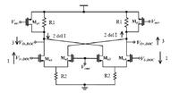
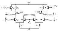
This circuit is used as dc offset canceller but I can't understand how it works.

it is the block diagram of circuit which you can see DC offset canceller in it:

In the paper it explains as below:
"In this design, a Ft doubler scheme is proposed for inclusion to the dc offset canceller, as shown in This structure cancels the dc offset voltage and simultaneously corrects the common mode voltages of the outputs of DOC to a desirable level Vcmr . The value Vcmr is chosen at the midpoint of the calculated input common voltage range and its voltage is fixed by the resistor ratio"
I can't understand the duty od Mp1 Mp2 and i don't know that all the transistors are in saturation region or not. and one more question it says that the output dc voltage is equal to Vcmr how could it be possible the dc voltage of input and output be equal?
could you please tell me how this circuit works and response my questions?
best regards
matin
This circuit is used as dc offset canceller but I can't understand how it works.

it is the block diagram of circuit which you can see DC offset canceller in it:

In the paper it explains as below:
"In this design, a Ft doubler scheme is proposed for inclusion to the dc offset canceller, as shown in This structure cancels the dc offset voltage and simultaneously corrects the common mode voltages of the outputs of DOC to a desirable level Vcmr . The value Vcmr is chosen at the midpoint of the calculated input common voltage range and its voltage is fixed by the resistor ratio"
I can't understand the duty od Mp1 Mp2 and i don't know that all the transistors are in saturation region or not. and one more question it says that the output dc voltage is equal to Vcmr how could it be possible the dc voltage of input and output be equal?
could you please tell me how this circuit works and response my questions?
best regards
matin


