Continue to Site

Welcome to EDAboard.com

Welcome to our site! EDAboard.com is an international Electronics Discussion Forum focused on EDA software, circuits, schematics, books, theory, papers, asic, pld, 8051, DSP, Network, RF, Analog Design, PCB, Service Manuals... and a whole lot more! To participate you need to register. Registration is free. Click here to register now.

[SOLVED] Why low efficiency in Wireless power transfer systems ?

Status
Not open for further replies.

nvt088

Member level 4
Member level 4
Joined
Dec 24, 2013
Messages
79
Helped
10
Reputation
20
Reaction score
10
Trophy points
8
Location
Jupiter
Activity points
509
Hi everyone.

I simulated and fabricated a WPT system using two loops (source and load) and two spiral coils (TX and RX) as showed in picture. The method is resonant coupling.
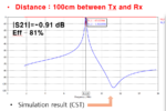
The simulated result is good. Efficiency at 1m is 80%.
However, my measured result is bad. Efficiency at 1m just 10%. I used Vector Network Analyzer for measurement.

Is there any reason for this low efficiency? Is it exact to use VNA for measuring efficiency because the input power of VNA is very low, 1W, right?

One more question, how to check up the resonant frequency for each loop and spiral coil? I want to make sure they have the same resonant frequency. Many thanks

WPT.png
 

I think your measurment environment is not proper because there may be some reflections,diffractions,scatterings from other objects in that environment.Especially metallic objetcs ( for instance your VNA ) will create some reflections with a phase changings and when these reflected,scattered waves have arrived to you receiver with different phases, they will probabaly create "beatings" and overall wave power will drop.
Instead, you should use antenna chamber to isolate these unwanted waves coming from different metallic and non-metallic objetcs.Rear reflected waves are also trouble.
 
If you use a solenoid or coil to transmit your power, a half of the power goes out backwards. You need to reflect this power forward so it is phase with the forward wave, like a reflector in a yagi aerial.
Frank
 
In the shown setup, the instrument near the coils and the table frame are probably disturbing the field.

Generally speaking, it's rather unlikely that the real circuit has identical behaviour as the simulation. At least, you'll need to tune the resonant circuits to factor in component tolerances.

Another question is if your simulation models the coil geometry and e.g. skin effect losses realistically.
 
  • Like
Reactions: nvt088

    nvt088

    Points: 2
    Helpful Answer Positive Rating
One more question, how to check up the resonant frequency for each loop and spiral coil? I want to make sure they have the same resonant frequency.

I see that you have the VNA on the desk. It is exactly what you need to find the resonant frequency of the coils.

How did you calculate 80% efficiency of power transfer at 1m distance? Sounds too good for me.
 
  • Like
Reactions: nvt088

    nvt088

    Points: 2
    Helpful Answer Positive Rating
To capture most the magnetic field lines of force the rule of thumb is the loop diameter must be twice the separation distance. and then you only get one side of the loop forces. After that inverse square loss from dispersion prevails. Resonant frequency is easily to scan and calibrate with a tuned high Q capacitor. ( polyester, polyurethane, mica or teflon)
 
  • Like
Reactions: nvt088

    nvt088

    Points: 2
    Helpful Answer Positive Rating
I see that you have the VNA on the desk. It is exactly what you need to find the resonant frequency of the coils.

How did you calculate 80% efficiency of power transfer at 1m distance? Sounds too good for me.

@vfone:

I used formula: efficiency = |S21|^2 . 80% is a simulation efficiency.

Unfortunately, the measurement efficiency is just 10%
 

I used formula: efficiency = |S21|^2 . 80% is a simulation efficiency.
The formula is correct. Can you show how you achieved this high efficiency in your simulation circuit? I doubt that it's possible with real components.

To capture most the magnetic field lines of force the rule of thumb is the loop diameter must be twice the separation distance. and then you only get one side of the loop forces. After that inverse square loss from dispersion prevails.

Assuming the setup is working at e.g. 10 or 15 MHz, only a small part of the power fed to the coil is actually "dispersed" or radiated to free space. Most of the energy is circulated between the magnetical near field and the resonant circuit. The real power is mostly burned in circuit losses. It's not theoretically impossible to capture more than 50 percent of feeded real power on one side of the coil, but I agree that it's difficult with the sketched geometry.
 
  • Like
Reactions: nvt088

    nvt088

    Points: 2
    Helpful Answer Positive Rating
The formula is correct. Can you show how you achieved this high efficiency in your simulation circuit? I doubt that it's possible with real components.

In my simulation:
Diameter of loop (source and load) is 30 cm.
Outer diameter of spiral coil is 60 cm, pitch 1cm, thickness of wire 0.5 cm.

At distance 1m between two spiral coils, I change that distance between loop and spiral coil, so efficiency in simulation is 80 %.

I guess that the cable of VNA for measuring can impact on result, right? Do you have any idea about de-embedding VNA?. Because I need to take S11, S21 at the position of source and load loop (not at VNA) because the length of cable is 0.5m.

Many thanks
 

In my simulation:
Diameter of loop (source and load) is 30 cm.
Outer diameter of spiral coil is 60 cm, pitch 1cm, thickness of wire 0.5 cm.

Metal loss included, or ideal conductors?
 
  • Like
Reactions: nvt088

    nvt088

    Points: 2
    Helpful Answer Positive Rating
|S11| or |S21| aren't be affected by shifting the reference plane (port extension). But it's a simple operation for all recent VNAs.

Is the transmission system designed for 50 ohm source and load impedance?
 

|S11| or |S21| aren't be affected by shifting the reference plane (port extension). But it's a simple operation for all recent VNAs.

Is the transmission system designed for 50 ohm source and load impedance?

Yes. I utilized 50 Ohm for source and load impedance. My HFSS result is almost same with CST simulation result. Just experimental result is low. :(
 

Do you have any idea to improve its efficiency?

You need to add snake oil.

Or you can start to troubleshoot the existing setup. Check the simulated and measured resonator Q factor, to understand the losses. Also, in simulation you can look at the simulated fields, and check if your lab environment (other metal etc) can be critical.
 

Status
Not open for further replies.

Part and Inventory Search

Welcome to EDABoard.com

Sponsor

Back
Top