KhaledOsmani
Full Member level 6

I`m having the old error of ADC.
I will state everything clearly here, hoping to get an effective reply:
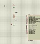
I've connected the LM35DZ, with 1k resistor, and supplied power into the circuit (supply voltage = 6.72V; note that this sensor has a range from 5 to 30VDC of voltages)
I've connected a multi-meter, one branch is connected to the output of the circuit, the other branch, is connected to the ground of the circuit, so basically here I`m testing the voltage that this circuit resulted.
Here the temperature is nowadays ranging from 20C to 23 DC.
What I see on the output voltage of the circuit is: 0.20V to 0.23V
Which means that the temperature is 100*output voltage of this circuit.
To make this more sure, I've placed this entire circuit in the refrigerator, this is what I've seen:
output voltage decreases like: 0.20 0.19 0.18 0.17 0.16 0.15 and so on
More over, I had lighted a lighter, near the sensor, and this is what I see on the output voltage:
0.20 0.25 0.30 0.55 0.58 and so on
Conclusion: This temperature sensor, is from a side, working and efficient. from another side, this whole circuit as I/O is efficient and working.
Now, concerning the micro-controller part, I`m using PIC18F4520.
I've set the PORTA to analog mode.
I've also set the PORTA to input mode.
Problem: I`m not seeing correct, or real values, of Temperature in C, on the LCD, and most of the times all I see is: 0C
This is the logic that I had used to convert from analog to digital:
put the converted value of the temperature in a special register, named for example tempdig
then I converted from digital to analog by multiplying the value inside tempdig by the factor 5/1023
due to observation, this multiplication isn't enough, there must be a multiplication of 100/2 then subtraction of 20 to get an accurate output.
When I connected the LM35DZ alone, it worked correct and great, but when adding more components of the circuit, it get stuck, or lost I can't give a logic expression about what happens to it, but It randomize, and get inaccurate.
This topic is not that hard, this problem is stuck with me for weeks, there is no intelligence in converting and outputting sensor readings on the LCD. Could any body please tell me what the problem is and its solution, is it me dealing with complexities in an in-efficient way?
NOTE that if this is solved, it remains problem with the LDR, and other other sensors...
I will state everything clearly here, hoping to get an effective reply:
I've connected the LM35DZ, with 1k resistor, and supplied power into the circuit (supply voltage = 6.72V; note that this sensor has a range from 5 to 30VDC of voltages)
I've connected a multi-meter, one branch is connected to the output of the circuit, the other branch, is connected to the ground of the circuit, so basically here I`m testing the voltage that this circuit resulted.
Here the temperature is nowadays ranging from 20C to 23 DC.
What I see on the output voltage of the circuit is: 0.20V to 0.23V
Which means that the temperature is 100*output voltage of this circuit.
To make this more sure, I've placed this entire circuit in the refrigerator, this is what I've seen:
output voltage decreases like: 0.20 0.19 0.18 0.17 0.16 0.15 and so on
More over, I had lighted a lighter, near the sensor, and this is what I see on the output voltage:
0.20 0.25 0.30 0.55 0.58 and so on
Conclusion: This temperature sensor, is from a side, working and efficient. from another side, this whole circuit as I/O is efficient and working.
Now, concerning the micro-controller part, I`m using PIC18F4520.
I've set the PORTA to analog mode.
I've also set the PORTA to input mode.
Problem: I`m not seeing correct, or real values, of Temperature in C, on the LCD, and most of the times all I see is: 0C
This is the logic that I had used to convert from analog to digital:
put the converted value of the temperature in a special register, named for example tempdig
then I converted from digital to analog by multiplying the value inside tempdig by the factor 5/1023
due to observation, this multiplication isn't enough, there must be a multiplication of 100/2 then subtraction of 20 to get an accurate output.
When I connected the LM35DZ alone, it worked correct and great, but when adding more components of the circuit, it get stuck, or lost I can't give a logic expression about what happens to it, but It randomize, and get inaccurate.
This topic is not that hard, this problem is stuck with me for weeks, there is no intelligence in converting and outputting sensor readings on the LCD. Could any body please tell me what the problem is and its solution, is it me dealing with complexities in an in-efficient way?
NOTE that if this is solved, it remains problem with the LDR, and other other sensors...