Continue to Site

Welcome to EDAboard.com

Welcome to our site! EDAboard.com is an international Electronics Discussion Forum focused on EDA software, circuits, schematics, books, theory, papers, asic, pld, 8051, DSP, Network, RF, Analog Design, PCB, Service Manuals... and a whole lot more! To participate you need to register. Registration is free. Click here to register now.

[SOLVED] AC coupled for PLL Reference

Status
Not open for further replies.

khungbopro

Member level 1
Member level 1
Joined
Jan 8, 2013
Messages
33
Helped
0
Reputation
0
Reaction score
0
Trophy points
1,286
Visit site
Activity points
1,485
I used 50MHz oscillator to make Reference for PLL. But, I didn't use a capacitor AC coupled between Ref and PLL, the DC current from Ref isn't blocked. Please help me to know in detail the influence of DC current to the output frequency !?!
Thank you!
 

The DC coupling could upset the bias on the PLL input stage AND the output amplifier in the oscillator. The effects could be anything, from nothing - perfect working to one or other of the stages being biassed off and no oscillator AC available. :-(
and magic smoke coming out of somewhere8-O
Frank
 
sorry,
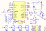
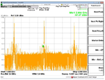
This is my design. I used MAX2870 to systhesis frequency (4.9GHz). I measured my circuit, but output frequency was incorrect. I don't know that DC current from Reference is cause wrong frequency or not ???
 

Attachments

  • 06-04-2014 2-26-46 AM.png
    06-04-2014 2-26-46 AM.png
    153.5 KB · Views: 173
  • 06-04-2014 2-37-59 AM.png
    06-04-2014 2-37-59 AM.png
    173.4 KB · Views: 176

You can program the PLL in order to set the MUXOUT pin as output of R-divider and then N-divider (have a look to table 6 on datasheet) to see, on the oscilloscope, if the problem is due to the reference or to the vco (f.i. instabilities due to the loop filter).
In your schematic you didn't mention anything about the reference oscillator (type:cmos, sinewave,etc and amplitude)
 
Some PLLs use RF input stages that are auto-biased
inverters (plain CMOS, or SCL/CML). These can't work
with 50 ohms to ground and a loe dBm input power,
the input will never cross threshold. These inputs
need DC blocking so the auto-bias can do its work
if the signal is normal 50-ohm RF, centered about
ground. They can, however, also be driven with a
normal bang-bang CMOS gate with no problem (and
often, superior phase noise if your edge rates are
kept sharp).
 
The C7050 outputs logic level clock to Vcc, and PLL accepts lower levels by AC couple and internal Vcc/2 bias. So direct or AC couple ought to be fine with 15 pF high impedance load expected on clock signal.

To debug this, you are going to have to probe each pin and read the chip specs to see if there are any discrepancies, for all inputs and outputs. Starting with the mixer output. If the serial data is not sent correctly to setup the Fractional N or Integer N ratio, obviously , it would fail.
 
3303Fig01.gif


Image above is the model of Ref in PLL ? I don't know that it should have Resistor or shouldn't use Resistor! :thinker:
 

The spectrum shows a fundamental at about 1.45 GHz with 2nd and 3rd harmonics.
Maybe the loop is not locked, or it is programmed for another frequency.
Which is the state of the LD (Lock Detect) output?

Z
 
3303Fig01.gif
Image above is the model of Ref in PLL ? I don't know that it should have Resistor or shouldn't use Resistor! :thinker:
Spec says Reference Frequency Input. This is a high-impedance input with a nominal bias voltage of VCC_DIG/2. AC-couple to reference signal.\....>>> So no resistor. Chip is self biased to Vcc/2... verify If not front end is damaged and diode clamped to both rails.ALSO spec says "REF_IN Input Sensitivity 0.7min VCCmax [VPP]" not Vp ... so ensure you do stay within limits. >>>>> Report Vtune and Set parameters for ADC etc.> SHow complete RF signal paths .. Keep short and use coax . Verify all RF inputs on scope
 
Last edited:
Status
Not open for further replies.

Part and Inventory Search

Welcome to EDABoard.com

Sponsor

Back
Top