Continue to Site

Welcome to EDAboard.com

Welcome to our site! EDAboard.com is an international Electronics Discussion Forum focused on EDA software, circuits, schematics, books, theory, papers, asic, pld, 8051, DSP, Network, RF, Analog Design, PCB, Service Manuals... and a whole lot more! To participate you need to register. Registration is free. Click here to register now.

[ARM] Rotary encoder interfacing with lpc2148

Status
Not open for further replies.

sundar11

Member level 1
Member level 1
Joined
Apr 16, 2014
Messages
41
Helped
2
Reputation
4
Reaction score
2
Trophy points
8
Activity points
272
Hi everyone
I am trying to interface a rotary encoder with lpc2148. i am unable to identify the pattern clockwise and antilclockwise. I am configuring P0.28 and P0.29 as Gpio and connecting it to the rotary encoder. if there is a change in the pins due to the rotary encoder state change it stands only in "low " or High. it doesnot follow any pattern as mentioned in the data sheet . Any suggestion or any idea about this would be helpful.


Regards

Sundar
 

Hi Sundar,

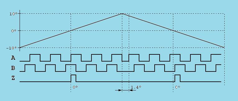
is it an encoder with incremental outputs ABZ(MFG?)? IF so A and B is 90 degree shifted in phase and a change in phase is a direction change. The pattern should look like

5500270900_1397664791.jpg


Enjoy your design work!
 
Hi HTA

Thanks for responding, Is all the Rotary encoders have the Same pattern as you mentioned in the attachment, or they differ according to their design.


Regards
Sundar
 

Hi Sundar,

that is the standard for incremental encoders. There are of course other interfaces, like analog Sine/Cosine or digital serial or parallel output. On the digital interface there are open standards, like the SSI/BiSS interface( https://biss-interface.com/ ) or proprietary interface (could be more then 10). If you have a datasheet from your encoder it should describe what is outputted.

Enjoy your design work!
 

Hi HTA
Thanks for your information. Now i will check the direction of the Rotary Encoder With this predefined Pattern.
 

hi everyone

The rotary encoder i am using does not follows the predefined pattern for clockwise and counterclockwise. The state of change gray code is like this 11->00->10->11, for both forward and reverse rotations. The Rotary encoder i use has 5 pins, pullup resistor value=10k. I have attached the code with this , can anyone suggest where i am going wrong.

Code C - [expand]
1
2
3
4
5
6
7
8
9
10
11
12
13
14
15
16
17
18
19
20
21
22
23
24
25
26
27
28
29
30
31
32
33
34
35
36
37
38
39
40
41
42
int main()
{  
    LCD_Init();
    LCD_Command(0x80);
    Display_String("rotary encoder");
    PINSEL1=0x00000000; // configuring all the pins as GPIO
        IODIR0 = 0xcfffffff;   // configuring pins as input
    while(1)
    {
    if((((IOPIN0)&(1<<29))==!(1<<29))&&(((IOPIN0)&(1<<28))==!(1<<28)))
        {
        LCD_Command(0xc0);
        Display_String("00");  
        delay();  
        }  
        else if((((IOPIN0)&(1<<29))==(1<<29))&&(((IOPIN0)&(1<<28))==(1<<28))) 
            { 
            LCD_Command(0xc0); 
            Display_String("11");   
            delay();  
            }  
            else if((((IOPIN0)&(1<<29))==(1<<29))&&(((IOPIN0)&(1<<28))==!(1<<28))) 
            { 
            LCD_Command(0xc0); 
            Display_String("10"); 
            delay();     
            }
                else if((((IOPIN0)&(1<<29))==!(1<<29))&&(((IOPIN0)&(1<<28))==(1<<28))) 
            {
            LCD_Command(0xc0); 
            Display_String("01"); 
            delay(); 
            }  
        }
}
 
void delay(void)
{
    int k ,m;
    for(m=0; m<60; m++);
    for (k=0; k<58; k++);
}

 
The state of change gray code is like this 11->00->10->11

This state switch 11->00 is quite unusual. Most popular Encoders, exhibits just 1 bit difference between neighbor states.


+++
 

hi andre_teprom

Thanks for responding , I checking the logic again
 

hi all
The part no of the rotary encoder i am using is EC11. it oddly behaves staying stable only in either 00 or 11. it pass through the states 01 and 11. what may be the issue. can any one suggest
 

Hi Sundar,

there are several types of EC11 ( datatsheet: **broken link removed** ). Which one you got?

Enjoy your design wok
 

I did not know the part number of the rotary encoder , but identified its model as EC11 from its physical structure.
 

hi everyone
I got the rotary encoder working , the code pattern for forward is 00->01->11->10->00, and for reverse the code pattern 00->10->11->01->00. i found out the pattern by configuring the pins as GPIO. i am using lpc2148.i need a suggestion , whether i need to continue to identify the pattern as configuring the pins as gpio or need to move to interrupt.


Regards
sundar
 

Status
Not open for further replies.

Similar threads

Part and Inventory Search

Welcome to EDABoard.com

Sponsor

Back
Top