Continue to Site

Welcome to EDAboard.com

Welcome to our site! EDAboard.com is an international Electronics Discussion Forum focused on EDA software, circuits, schematics, books, theory, papers, asic, pld, 8051, DSP, Network, RF, Analog Design, PCB, Service Manuals... and a whole lot more! To participate you need to register. Registration is free. Click here to register now.

Pure sinewave SPWM inverter

Status
Not open for further replies.
Mr. BaWa,

Here is the schematic for my DC-dc converter


I however used 4 Mosfets ie. I paralleled one with the high side Mosfet and the other with the lowside Mosfet

And by in series with the h-bridge you mean in series with the inductor?


I got a 75W, 120V incandescent bulb and connected it cross the 10uF,400V electrolytic capacitor and it did not light up and the transformer began to make a sound and the voltage fell from 180Vdc to about 2Vdc. What could be the problem????

could it be because the electrolytic cap doesnt have a low ESR?


Please help!!!
 
Last edited:

Mr. BaWa,

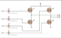
Here is the schematic for my DC-dc converter


I however used 4 Mosfets ie. I paralleled one with the high side Mosfet and the other with the lowside Mosfet

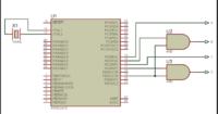
Here is the SPWM section I'm using that I found from another site:

For the signals from the MCU as we discussed in previous post that the SPWM should go to the high-side MOSFETs and the fundamental frequency to the low side MOSFETs so that diagonal MOSFETs switch on at the same time so not shown in the diagram

signal A should go to Q4 instead of Q1
signal B should go to Q2 instead of Q4
signal C should go to Q3 instead of Q2
signal D should go to Q1 instead of Q3


Further,
When I remove the heat sink off my MOSFETs (N.B.all four FETs were connected to one heat sink) and connect the 180Vdc DC link or DC bus to the drains of the 2 high-side FETs, the noise stops from the ferrite transformer as mentioned earlier but the leds in the circuit (that are used just to indicate the presence of current) and even my laptop screen starts to flicker and when I measure across the cap parallel to a 20W bulb I get about 15VAC.

Whats wrong here???
 
Last edited:

Kryptone said:
I however used 4 Mosfets ie. I paralleled one with the high side Mosfet and the other with the lowside Mosfet
this is a push pull topology and the mosfet shown in 1st figure all are low side .
and first of all your DC DC stage is not working , so you have to fix the problem first and then move to H bridge stage.
so have u connected all the four mosfet of DC DC stage to the same heat sink ? if yes , have you used a silicon pad or insulating pad between mosfet and heatsink (mosfet upper body(metal ) is connected to drain terminal ). so either use 2 heat sink for 2 banks or use insulating pads for 1 heat sink .
do let me know , so that i can come to any conclusion.
 

yes I used pushed pull for dc-dc converter I just paralleled the other two MOsfet to try and acheive more power. The heat sink was actually for the h bridge I did not use a heat sink for the FETs in the dc-dc stage.I took the heat sink from an old computer SMPS and yes it has insulating pads on it.

So you are saying that for the push pull dc-dc converter that I am using both are low side?? I'm confused I was sure one is high side and the other low-side.

So could that be apart of the problem but it works giving me 180 Vdc across the capacitor of the LC filter. The capacitor is 10uF, 400V and I'm not sure of the value of the inductor.

I was thinking that maybe the inductor is not at the right value to filter the 50 kHz down to a low frequency like about 400-700 Hz or maybe something is wrong with the inductor. Could frequency in terms of synchronization with the full bridge be the problem here???

but then again it didnt work with the 75W bulb either so perhaps impedance of the LC filter resonance cld be a problem or mabe the transformer is damaged because I supply about 14V from a power supply to the dc-dc converter and the voltage drops to about 12V and I know its the transformer because when I disconnect it the voltage is 14V as provided and when I connect it the voltage drops slightly...............
 
Last edited:

180 Vdc across the capacitor of the LC filter
It should be AC, not DC.
Inverter have different working sections. Each can be tested separately. First you produce 180V DC_bus. This section, you say is working. Don't connect h-bridge for now. Dc bus has its own filter capacitor, from where h-bridge will be connected.
Test DC converter if it can deliver the full wattage by connecting load, such as bulb, your soldering iron etc. Check the voltage drop with increasing load. Let it operate for few minuets If it works ok, the ferrite transformer and FETs does not heat excessively.
Now, the AC converter, only connect micro controller and FET driver section to 12V DC and check with oscilloscope or multi-meter for gate signals. Are they the same as expected.
Now connect 12V-DC to h-bridge, not 180V, and check if 8V-AC on H bridge output. You can remove LC-filter to see if it is not causing problem. Most probably your h-bridge has a short circuit. It should not draw current from 12V supply, when there is no load on its output. Monitor current, it draws with multi-meter, putting it in series with +12V.
If all works well now you can connect with 180V-DC but put the bulb in series with +180V and +ve wire to hbridge. Bulb will light up if there is short in it. This will protect mosfets of hbridge and DC converter(you have already made smoke out of ferrite transformer). Check for 120V-AC on hbridge output. Now you can remove bulb and connect directly to +ve 180V. Put load on hbridge output. Check if it supports full load and FETs don't heat-up. Now you can check output waveform with different loads.
 

ALERTLINKS said:
It should be AC, not DC.
I think Kryptone is talking about DC DC stage output filter , so it should be 180v DC there , but the problem is ,when he connect a Load to DC DC stage output ,the voltage drops significantly , which means that the DC DC stage is not working properly.

Kryptone said:
but then again it didnt work with the 75W bulb either so perhaps impedance of the LC filter resonance cld be a problem or mabe the transformer is damaged because I supply about 14V from a power supply to the dc-dc converter and the voltage drops to about 12V and I know its the transformer because when I disconnect it the voltage is 14V as provided and when I connect it the voltage drops slightly.
let me do some calculations for you, you have connected a 75 watt 110v rating bulb at the output ,so the resistance of filament of the bulb is 161.3ohms(using ohms law ). and the converter output voltage is 180vdc .so the bulb will consume approx (V/R) i.e 180/161.3 =1.11 ampere.
now come to the transformer input current, as you know the relation
[ i1 / i2 = v2 / v1]. where v2 should be 180, v1 should be 12 and i2 is 1.11 , so if you calculate i1 . it will be 16.6 ampere , so you must connect the input of DC DC stage to a BATTERY or a power supply capable of providing atleast 16 ampere.
i doubt if your power supply can provide this much of current at 12v , so i strongly recommend to use a 12v battery (of ups or inverter).
also check the gate voltage of the mosfet , and let me know .
 

I think Kryptone is talking about DC DC stage output filter , so it should be 180v DC there , but the problem is ,when he connect a Load to DC DC stage output ,the voltage drops significantly , which means that the DC DC stage is not working properly.


let me do some calculations for you, you have connected a 75 watt 110v rating bulb at the output ,so the resistance of filament of the bulb is 161.3ohms(using ohms law ). and the converter output voltage is 180vdc .so the bulb will consume approx (V/R) i.e 180/161.3 =1.11 ampere.
now come to the transformer input current, as you know the relation
[ i1 / i2 = v2 / v1]. where v2 should be 180, v1 should be 12 and i2 is 1.11 , so if you calculate i1 . it will be 16.6 ampere , so you must connect the input of DC DC stage to a BATTERY or a power supply capable of providing atleast 16 ampere.
i doubt if your power supply can provide this much of current at 12v , so i strongly recommend to use a 12v battery (of ups or inverter).
also check the gate voltage of the mosfet , and let me know .

For High side
Drain wrt Gate 11.8V
Drain wrt GND 11.8V
Drain wrt source 7.6V

For low side
Drain wrt source 11.76V then after awhile I check again and get 5V
Drain wrt gate 6.4V then after awhile I check again and get 3.6V
Drain wrt GND 11.4V then after awhile I check again and get 5V

but across 10uF cap I get 181.9 Vdc which is what I should get. I think I am going have to sort out the input current.


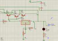
At the input of the dc-dc converter, I am using a 12-0-12 V, 2A transformer and I paralleled 3 TIP42C with the collectors to the output of a LM317 and the emitters to the input and a resistor at the base of the transistor. I simulated this in Proteus and got 15A but by using a single and double cell battery in Proteus. Therefore I think I should be getting 15A but it seems am not getting that.

Here it is:


Also, I placed a 20W, 110V bulb at the output of dc-dc converter and it lit up with no noise or smoke from the ferrite transformer the noise is only heard with the 75W bulb.

Could the value of L or C need to be changed to drop the 50 KHz through the transformer to a much lower frequency?? could this cause flickering of the bulb when connected in series between +180Vdc and the drain of h-bridge???
 
Last edited:

It should be AC, not DC.
Inverter have different working sections. Each can be tested separately. First you produce 180V DC_bus. This section, you say is working. Don't connect h-bridge for now. Dc bus has its own filter capacitor, from where h-bridge will be connected.
Test DC converter if it can deliver the full wattage by connecting load, such as bulb, your soldering iron etc. Check the voltage drop with increasing load. Let it operate for few minuets If it works ok, the ferrite transformer and FETs does not heat excessively.
Now, the AC converter, only connect micro controller and FET driver section to 12V DC and check with oscilloscope or multi-meter for gate signals. Are they the same as expected.
Now connect 12V-DC to h-bridge, not 180V, and check if 8V-AC on H bridge output. You can remove LC-filter to see if it is not causing problem. Most probably your h-bridge has a short circuit. It should not draw current from 12V supply, when there is no load on its output. Monitor current, it draws with multi-meter, putting it in series with +12V.
If all works well now you can connect with 180V-DC but put the bulb in series with +180V and +ve wire to hbridge. Bulb will light up if there is short in it. This will protect mosfets of hbridge and DC converter(you have already made smoke out of ferrite transformer). Check for 120V-AC on hbridge output. Now you can remove bulb and connect directly to +ve 180V. Put load on hbridge output. Check if it supports full load and FETs don't heat-up. Now you can check output waveform with different loads.

ALERTLINKS,
I tested the FET driver and MCU stage with 12V and I get square waves generated by the MCU. Also, when I use 12V to h-bridge I get 12-15V-AC when I place a 20W,110V bulb in series between +ve wire of +180Vdc and to drain of h-bridge the bulb flickers and the output AC fluctuates as well.

Could the value of L or C need to be changed to drop the 50 KHz through the transformer to a low frequency?? could it cause the flickering???
 
Last edited:

Kryptone said:
For High side
Drain wrt Gate 11.8V
Drain wrt GND 11.8V
Drain wrt source 7.6V
which stage are you talking about ?i was talking about DC DC stage . i have already said that there is no high side mosfet configuration in push pull, so how have you written the high side mosfet configuration . ?
i just wanted to know the gate to source voltage of mosfet of DC DC converter stage ?
Kryptone said:
At the input of the dc-dc converter, I am using a 12-0-12 V, 2A transformer
i think u havn't gone through post #27 , i have clearly calculated the input power supply configuration.
Kryptone said:
Could the value of L or C need to be changed to drop the 50 KHz through the transformer to a much lower frequency?? could this cause flickering of the bulb when connected in series between +180Vdc and the drain of h-bridge???
Follow the instructions given in post #27 .
 

which stage are you talking about ?i was talking about DC DC stage . i have already said that there is no high side mosfet configuration in push pull, so how have you written the high side mosfet configuration . ?
i just wanted to know the gate to source voltage of mosfet of DC DC converter stage ?

i think u havn't gone through post #27 , i have clearly calculated the input power supply configuration.

Follow the instructions given in post #27 .

Therefore if there is no high side that means that there is no need for a boot strap capacitor at Q1 in post #23 because I treated Q1 like a high side. I used the IR2110 between the SG3525 and the FETs however in post 23 there is no mosfet driver.

Also, I measured the gate to source voltage and for Q2 I got VGS= 0.8V and for Q1 I got nothing for VGS.

The values I outlined in my previous post were for Q1 qnd Q2 of dc-dc converter respectively.
 
Last edited:
u r right there is no need of bootstrap circuit , the schematics shown in post # 22 ,https://obrazki.elektroda.pl/8827873100_1396903703.html is practical . so you can make it as it is ,and dont add bootstap circuit in it ,,,
and also your power supply current rating is not sufficient ,so if u manage to make the circuit , u can't drive a 75 watt bulb trhrough it . Use a 12v battery of capacity > 7ah atleast for testing purpose.


SO then can I still use the IR2110 because I already did the PCB? and if I use it then should I connect it for 2 low sides as you sid they are all low side and since there there is no high side?
 

i have never tried to use IR2110 only for low side drive , its a HIGH LOW side driver IC , you can try it ,,,one more option for you ,in your pcb you can bypass the input pin to the output pin of IR2110, and remove the ic , after doin this tell me the gate to source voltage ?
and i will also suggest some low side driver ic or totem pole driver between sg3525 and mosfet bank, because u r using 2 mosfets in parallel , so there might be a possibility that SG3525 cant provide enough current to drive the mosfet gate . to turn the power mosfet fully ON ,ensure that Vgs should be greater than 8V.
 

https://obrazki.elektroda.pl/4300095000_1396940505.png

In this picture Q1 and Q3 are high side FETs.
DC-DC converter has push-pull stage. It is h-bridge where IR2110 drive it with inputs from microcontroller..

Refer to your first post,
The dc-dc converter worked and now I am on to the SPWM section where I am using the ATmega16 to generate the SPWM signals .
and the picture there of h-bridge.

There I suggested to use IR2110 and not with DC-DC converter. DC converter you already told, was working.

https://obrazki.elektroda.pl/4300095000_1396940505.png

Make your circuit like this . Use 12V instead of 300V or 180V. Forget about LC filter. First achieve the right output from h-bridge.
 

still getting for Q2 Vgs=0.8V and for Q1 Vgs=0V
 

Check the output waveform of sg3525 on oscilloscope...(pin11 and pin14)
 

Most common mistakes are overlooking the need for a deadband on gate control causing smoke from cross conduction failures under worst case conditions, excessive RdsON values for MOSFETS. and core saturation.
 

i have never tried to use IR2110 only for low side drive , its a HIGH LOW side driver IC , you can try it ,,,one more option for you ,in your pcb you can bypass the input pin to the output pin of IR2110, and remove the ic , after doin this tell me the gate to source voltage ?
and i will also suggest some low side driver ic or totem pole driver between sg3525 and mosfet bank, because u r using 2 mosfets in parallel , so there might be a possibility that SG3525 cant provide enough current to drive the mosfet gate . to turn the power mosfet fully ON ,ensure that Vgs should be greater than 8V.


BaWa,

I disconnected the transformer and checked the output from the SG3525 on the oscilloscope and I get the square waves. What is the voltage I should get from output A and output B? I checked and got 4.3V from them with VCC= 11.23V is that ok? However, when I coonect the transformer the square wave ie. the duty cycle gets smaller. I still get Vgs=0V for Q1 and Vgs= 0.8V for Q2. Therefore, from this I know the MOSFET are not fully ON which they are supposed to be right?

Also, what is the purpose of the 2200uF capacitor connected to the centertap of the ferrite transformer?
 
Last edited:

It means that your driver stage is not working properly , try to check the connections again , and try to replace sg3525 with a new one ,
have you implemented a proper feedback loop ?
again check the Vgs on oscilloscope when transformer is connected , and tell me the dutycycle and voltage based on observation for both the mosfet ,
its more unlikely that the resistor or capacitor got damaged , so the only thing that gets easily damaged is SG3525 and Mosfets, also make sure that your mosfets are not damaged ,so before replacing the IC ,ensure that mosfet are in working condition ,otherwise your new ic will also damage. i strongly doubt that the mosfets might got damaged because you have already witnessed the smoke coming out from transformer . so i will suggest to replace all the mosfets and the ic ,
Kryptone said:
Also, what is the purpose of the 2200uF capacitor connected to the centertap of the ferrite transformer?
It is used on dc link to minimise the spikes and current ripples, it should be placed near your power stage.
 
Status
Not open for further replies.

Similar threads

Part and Inventory Search

Welcome to EDABoard.com

Sponsor

Back
Top