Continue to Site

Welcome to EDAboard.com

Welcome to our site! EDAboard.com is an international Electronics Discussion Forum focused on EDA software, circuits, schematics, books, theory, papers, asic, pld, 8051, DSP, Network, RF, Analog Design, PCB, Service Manuals... and a whole lot more! To participate you need to register. Registration is free. Click here to register now.

Mosfet isn't ... Mosfetting... :-)

Status
Not open for further replies.

mnvelocitypilot

Junior Member level 1
Joined
Mar 4, 2014
Messages
18
Helped
0
Reputation
0
Reaction score
0
Trophy points
1
Activity points
216
Hi Team - I could sure use some input on this...

I'm working on a replacement strobe system for my experimental Velocity aircraft... I've been getting stuck on using an IRF1501 N channel power Mosfet to switch on and off the approximately 2 amps I'm using to drive 5 10W Cree LEDs.... But I can only get about 0.9A through the Mosfet. Essentially, it's almost like the Mosfet is in an active range instead of saturated.

... Here's the setup:

The current limited supply connected to the LED anode is around 16 volts
The LED cathode is connected to the Mosfet Drain
The Mosfet Source is grounded.... and,
The Mosfet Gate is driven by a PIC controller.

The measured voltages are as follows:
Vds = 3.2V (wow.... with a spec'd Mosfet internal resistance of around 0.4 ohms, and a drain to source current measured at only 0.9A, that seems mighty high... more like an internal resistance of 3.5 ohms...)
Vgs = 4.94V (seems about right)
Vdg = 1.72V (which makes sense... Vdg + Vds = about Vgs)

So... Why in the heck is there such a huge voltage drop across the Mosfet? Why isn't it conducting my full supply current of about 2A? Why, why WHY???

BTW, I'm planning to up the current if I can get this thing going to about 4.8 - 5 Amps... which is why I chose not to use a Mosfet and not a power transistor...

Any thoughts would be REALLY appreciated... I'm stuck!

Thanks.
 

www.datasheetarchive.com has never heard of an IRF1501 Mosfet.

Most Mosfets are barely turned on when their Vgs is only 5V, they need 10V to fully turn on.
Since your Mosfet is driven with only 5V from a PIC then you should use a "logic level" Mosfet that fully turns on when its Vgs is 4.5V or 5.0V.

Please post your schematic so we can see if and how you are limiting the current in the LEDs. It sounds like you are hoping that the 2A power supply will limit the current without burning up and burning out the LEDs.
 
I would suggest a transistor-MOSFET pair. MCU driving the Transistor and the Transistor driving the MOSFET. Like @Audioguru said above it's likely that the MOSFET Is not properly turned ON.
 
Hey, thanks very much for the response!

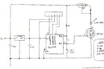
As you can see from the schematic, this is a very (very) simple design. I selected the particular mosfet, IRF1501, because it's spec'd VGS(th) Gate Threshold Voltage is a maximum of 4.0V, and as you can see I'm driving it with 4.9V... so, I should be operating it within spec, and I think I should see the spec'd Rds(on) of 0.055 ohms...

So... am I reading the spec wrong?

I can add an NPN transistor to level shift the PIC controller TTL level output to the ship power rail... but, in theory, it shouldn't be needed, and in an aircraft I've learned to avoid things that could fail but aren't really needed..

I'm using an LM338 for current limiting... but I'm looking at various buck topologies... that isn't an easy reach because in my installation the regulator has to be a fair distance from the load.

Anyway, here's the schematic... would much appreciate your thoughts!
 

sorry, for some reason the schematic didn't upload... trying again...

IMG_2379.JPG
 

Can you provide a link to the datasheet of the mosfet you are trying to use?
 

Thanks, alexan_e - can you explain what you mean by "high side switch"? Do you mean having the switch (in this case the mosfet) between the load and the rail?

Thanks again - very much appreciated!
 

Is it an ARF1501? What is Vin? Your pullups to the PIC I/O go to Vin and not the supply to the PIC.
 

Thanks, alexan_e - can you explain what you mean by "high side switch"? Do you mean having the switch (in this case the mosfet) between the load and the rail?

Thanks again - very much appreciated!

After seeing your schematic that comment doesn't apply.

High side switch is when the control device is used in the positive supply side of the load, low side switch when it is used in the ground side of the load (like in your case)
**broken link removed**
 
Thanks! Here you go:

http://www.allcomponents.ru/fairchild/irf150153.htm

- - - Updated - - -

Vin is about 14V (the electrical system is essentially the same as a car - alternator, regulator, etc.). I use a 5V regulator to provide power to the PIC controller. And... You are Correct... the schematic is wrong (down level)... there is no pullup on the output of the PIC that drives the mosfet. Here's the correct level - my bad! Sorry!IMG_2380.JPG

I'm a putz and should have caught that. My bad!
 

Looks to me like the substrate diode on the PIC is limiting the MOSFET gate voltage (as your measurement indicates). Vgs of 5V is not enough to turn the MOSFET fully on (see data sheet). See #2 and #3 above.
 
Last edited:

The measurements I supplied in the original post were taken directly off the leads of the mosfet:
Vds = 3.2V
Vgs = 4.94V
Vdg = 1.72V
But, boy are you right... it just doesn't seem like the mosfet gate voltage is high enough even though I'm exceeding the max spec'd Vgs(th) threshold voltage of 4.0V... very confusing!
 

Analog Ground wins with what's got to be the right answer - followed closely by Audioguru! To both of you - thanks very much, I was reading the spec wrong... Audioguru said it best "The threshold voltage Vgs(th) of a Mosfet is when it is almost turned OFF not when it is properly turned on."

I really appreciate all the help. I'll redesign using a NPN transistor to level shift to the ship power rail (around 14v). That oughta do it!

In case anyone is interested, this project is to replace the landing light in my airplane with something that's at least as bright, but that can be put into "flashing mode", to help other aircraft see me coming.

Here's a short video of the airplane on a recent trip: https://www.youtube.com/watch?v=X8jpKQFkxxo

Again - thanks to all! MUCH appreciated!
 

If you add a common-emitter transistor as a level-shifter then the light will turn off when you want it on because the transistor will invert the signal. re-program the PIC to allow the invert.

You have a very nice Canard (quack, quack!) airplane. I have seen plenty of airplanes but never a Canard.
 
Just for clarification, 'threshold' means just that, the point at which conduction starts, below it there is negligible conduction, above it there is some conduction. You need to refer to the data sheets to find the minimum gate to source voltage that allows it to pass the current you need.

Brian.
 
One more thing. The pullup to the RA4 input should connect to the PIC supply, Vdd, and not Vin.
 

Status
Not open for further replies.

Part and Inventory Search

Welcome to EDABoard.com

Sponsor

Back
Top