CiccioB
Newbie level 4

Hello,
I have looked for a solution to this problem everywhere, but I could not find any solution.
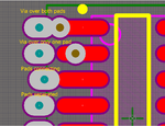
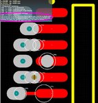
I am trying to create a custom footprint with some custom pads. These pads are nothing special: they are a joining of 2 elementary pads. One pad is only on the top layer, the second is a multilayer pad, so it has a hole.
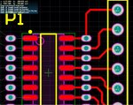
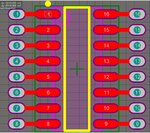
The idea is to have a SMD footprint with added pass-through pads at the SMD pads extremes.
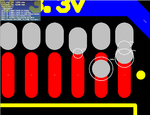
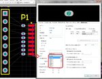
However I cannot find a way to connect those 2 pads. Even if they have the same designator number and Jumper ID, you cannot overlay them, nor you can add a trace between them. Once you use the footprint in PCB designer, you have lots of short circuit warnings.
The only workaround to this limitation is to keep the pads separated and then join them in PCB designer. Which is not really elegant nd you can't achieve the wanted pad form.
A am missing something or Altium Designer cannot understand when two pads are the same and thus apply to each of them the entire project rules so it detects short circuits, clearance and all other rule violations?
It is really not comfortable to go and create an exception rule for each footprint created and added to the design with such "double" pads. So there's some other workaround for this limitation?
Thanks in advance

