MahmoudHassan
Full Member level 6

- Joined
- Oct 4, 2010
- Messages
- 349
- Helped
- 44
- Reputation
- 90
- Reaction score
- 40
- Trophy points
- 1,328
- Activity points
- 3,919
Hi
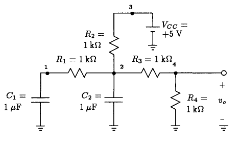
i used two method to set the initial conditions for the node V(1) for the following circuit

the first one i used this statement to insert initial condition on the capacitor
C1 1 0 1uF IC=+1V
and then used flag UIC
.TRAN 500us 10ms 0ms 500us UIC
full statement file :
The second one
i used only this statement to set initial condition
.IC V(1) = +1V
There is something wrong i don't understand the outputs from both netlists weren't the same !!!
for the first one The voltage of node 2 V(2) starts from zero as supposed

for The second statements the output was different !
and the voltage at node 2 didn't begin from Zero as supposed but 2.4 V
and V(1) starts from Zero (Which had initial value of 1V)

so i hope you can help me
Thanks a lot for your time
i used two method to set the initial conditions for the node V(1) for the following circuit

the first one i used this statement to insert initial condition on the capacitor
C1 1 0 1uF IC=+1V
and then used flag UIC
.TRAN 500us 10ms 0ms 500us UIC
full statement file :
Code:
Investigating Initial Conditions Established by SPICE
VCC 3 0 DC 5V
C1 1 0 1uF IC=+1V
C2 2 0 1uF
R1 1 2 1Kohm
R3 2 4 1Kohm
R2 3 2 1Kohm
R4 4 0 1Kohm

.TRAN 500us 10ms 0ms 500us UIC

.PLOT TRAN V(1) V(2) V(4)
.PROBE
.END
The second one
i used only this statement to set initial condition
.IC V(1) = +1V
Code:
Investigating Initial Conditions Established by SPICE
VCC 3 0 DC 5V
C1 1 0 1uF
C2 2 0 1uF
R1 1 2 1Kohm
R3 2 4 1Kohm
R2 3 2 1Kohm
R4 4 0 1Kohm

.TRAN 500us 10ms 0ms 500us
.IC V(1) = +1V
.PLOT TRAN V(1) V(2) V(4)
.PROBE
.END
There is something wrong i don't understand the outputs from both netlists weren't the same !!!
for the first one The voltage of node 2 V(2) starts from zero as supposed

for The second statements the output was different !
and the voltage at node 2 didn't begin from Zero as supposed but 2.4 V
and V(1) starts from Zero (Which had initial value of 1V)

so i hope you can help me
Thanks a lot for your time


