Continue to Site

Welcome to EDAboard.com

Welcome to our site! EDAboard.com is an international Electronics Discussion Forum focused on EDA software, circuits, schematics, books, theory, papers, asic, pld, 8051, DSP, Network, RF, Analog Design, PCB, Service Manuals... and a whole lot more! To participate you need to register. Registration is free. Click here to register now.

Need explanation in servo motor interfacing with pic16f877a using pwm

Status
Not open for further replies.

rangerskm

Full Member level 4
Full Member level 4
Joined
Jan 23, 2013
Messages
199
Helped
0
Reputation
2
Reaction score
0
Trophy points
1,296
Activity points
2,663
compiler used -hi tech c .20 mhz osc

Hi friends,just nw i started to learn servo motor ,but not able to understand the concepts,

1)actually we are giving the pwm signal to the motor how we can pass the pwm signals in to it??
2)please explain me the given code for servo control .


Code:
#include<pic.h>
#define _XTAL_FREQ 20000000
#define SRV RC0
 char ch,duty=0;
unsigned int servo_h=0;
void interrupt isr()
{
 if(TMR1IF)
{
TMR1IF=0;
TMR1H=0xff;
      TMR1L=0x54;
      TMR1ON=1;
servo_h++;
}
if(servo_h<=duty) SRV=1;
else SRV=0;
if(servo_h>500)
{
servo_h=0;
}

}
void main (void)

{
 int x=500;

TRISC=0x80;PORTC=0;
SPEN=1;CREN=1;SYNC=0;BRGH=1;SPBRG=129;
TMR1IE=1;TMR1IF=0;
GIE=1;PEIE=1;
TMR1H=0xff;
 TMR1L=0x54;
   TMR1ON=1;
TMR1IF=1;
duty=37;
__delay_ms(1000);
duty=25;
while(1);
}
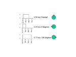
 

is your circuit follow this sequence?
controller -> motor driver -> servo motor.

and motor driver can be any driver like l293d.

and for pwm use following sequence.
servo2.jpg
 

no driver used here .
i dont know to give values for generating pwm .can u explain with formula and calculation
 

You have to configure CCP1CON register to generate PWM. Read datasheet. Generate a PWM of say 2 or 3 KHz and then vary the duty cycle to control the speed of servo motor. You need L293. The first o/p pair of L293 connects to motor and the first pair of inputs connect to MCU. The EN pin of first channel of L293 connects to CCP1 pin of MCU. IN1 and IN2 controls the direction of motor and EN controls the speed of motor.
 

You have to configure CCP1CON register to generate PWM. Read datasheet. Generate a PWM of say 2 or 3 KHz and then vary the duty cycle to control the speed of servo motor. You need L293. The first o/p pair of L293 connects to motor and the first pair of inputs connect to MCU. The EN pin of first channel of L293 connects to CCP1 pin of MCU. IN1 and IN2 controls the direction of motor and EN controls the speed of motor.

is it really necessory to use l293d?
bcoz in some tutorials direct connection shown but at some they uses l293d.
 

Motor draws 650 mA to 1 A. MCU can source or sink only 25 mA. L293 is needed. L293D's current rating is 650 mA and L293's is 1 A. It is better to use L293 because if motor draws 550 mA then L293D will heat up as current is more than 50% of its max ratings.
 

please use a driver ic like uln2008. then drive the motor it will manage the power, current and voltage problems.

as usually you can control the motor
 
whats the difference between uln2008 and l293
 

whats the difference between uln2008 and l293


l293 gives 600 mA, uln 2008 provides 500mA, l293 is h-bridge construction. uln2008 is made by darlington pair... u can control 2-3 motors and operate them simultaneously in any direction in l293. in uln u can use maximum 0f 8 motors simultaneously ....

- - - Updated - - -

basically pwm mode in pic is used to make the motor in different speeds. just connect one terminal of motor in direct voltage what is needed to that and the another end (ground side) should be given at the uln2008. see uln 2008 data sheet. by giving high voltage the grounding of motor is less, so it goes to less rpm, if low voltage is given at the ground, rmp increases. the main advantage of pwm is its switching speed.

imagine that if u r programming for switching the motor that single statement will eat few ms for the progress. in pwm that will be reduced.

Pulse-width modulation is an effective method for adjusting the amount of power delivered to an electrical load.

for pwm technique the uln2008 is very effective.

- - - Updated - - -

Ton of the pwm is directly proportional to the speed.

- - - Updated - - -


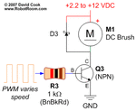
instead of that npn transistor we r using uln2008.
assume that
op of uln as collector of npn , and ip of uln as base of npn.

- - - Updated - - -

MotorSpeedControlSchematic.gif
instead of that npn transistor we r using uln2008.
assume that
op of uln as collector of npn , and ip of uln as base of npn.
 

thanks thirunavukarasu ,you really helped me a lot .

actually the pulse of servo motor is below 1khz right?? so we are not able to use ccp module in pic as it generates pwm of above 1 khz isnt ??please explain the correct concept of ccp module with reference to it.
 

The abbreviation CCP stands for Capture/Compare/PWM.

The CCP module is a peripheral which allows the user to time and control different events.
ccp includes pwm in it...
Capture Mode, allows timing for the duration of an event.
Compare Mode compares values contained in two registers at some point. One of them is the timer TMR1 register.

see this link , u will get a clear idea https://www.mikroe.com/chapters/view/6/

- - - Updated - - -

and another one.... u r not directly giving pwm signal to the motor.... u r giving pwm signal to the transistor which drives the motor. so u can use it. just try it. experimentally. them u will get it.
 
Status
Not open for further replies.

Part and Inventory Search

Welcome to EDABoard.com

Sponsor

Back
Top