cjrathi
Member level 2

Hi,
I have designed 90dB RF Attenuator using three Peregrine PE43703 30dB parts.
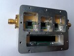
This design has been enclosed in a metal case (snapshot attached). Hence body mount SMA connectors are used for input and output.
As seen in the snapshot, all three stages are getting shielded by the metal compartment. Shielding from top has been achieved from the lids on top tightly screwed.
This design works fine till 90dB attenuation in 2-3 GHz range giving good step linearity. But I am facing issues in 5-6 GHz band.
Issues are:-
When stage 1 and 3 are set to full attenuation (60dB), it works fine. But when stage 1 and 2 are set, there is linearity issues in 5-6 GHz. i.e., setting 60 dB attenuation, total attenuation at 5.15GHz, 5.5GHz and 5.85Ghz are 67dB, 67dB and 68.1dB (considering 7dB insertion loss in this range). At 5.85GHz freq, ideally it should be also 67dB.
After this, keeping 1st and 2nd stage to full attenuation, when 3rd stage is varied from 0 to 30dB, this non-linearity is increased giving drastic degradation in S21 even at 5.15GHz and 5.5Ghz freq.
As per my study, the issue could be:-
1. Signal is getting leaked somewhere from RF path.
2. There could be an impedance mismatch of RF trace below the tunnel. (??)
3. Possibility of forming a waveguide/resonant box which is leaking the signal from input to output. (??)
4. Stage to stage coupling through ground planes (??)
5. Leakage through body mount SMA connector (??)
Please suggest the reason of this issue and possible solution to minimize those effects..
Thanks,
CR


