Continue to Site

Welcome to EDAboard.com

Welcome to our site! EDAboard.com is an international Electronics Discussion Forum focused on EDA software, circuits, schematics, books, theory, papers, asic, pld, 8051, DSP, Network, RF, Analog Design, PCB, Service Manuals... and a whole lot more! To participate you need to register. Registration is free. Click here to register now.

Calibrating Digital Multi Meter with Voltage ref

Status
Not open for further replies.

jonnybgood

Full Member level 4
Full Member level 4
Joined
Dec 28, 2010
Messages
214
Helped
3
Reputation
6
Reaction score
1
Trophy points
1,298
Activity points
3,011
Hi,
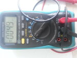
I have this Kyoritsu DMM which I owned for 4 years now. This year I will be using it to take some accurate measurements for my school project.

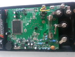
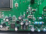
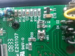
I need to calibrated it with reference voltages if possible. Attached are some photos of the circuit with 2 trimmer pots. I need to knows which is what.

I appreciate if you can share some practical methods of calibrating such a DMM.

thanks

jonny
 

Attachments

  • IMG_20130914_122631.jpg
    IMG_20130914_122631.jpg
    1.6 MB · Views: 143
  • IMG_20130914_121824.jpg
    IMG_20130914_121824.jpg
    2.3 MB · Views: 149
  • IMG_20130914_121858.jpg
    IMG_20130914_121858.jpg
    2.7 MB · Views: 146
  • IMG_20130914_121911.jpg
    IMG_20130914_121911.jpg
    2.3 MB · Views: 153

the voltage calibration can be made on highly accurate lab powersupply, if your meter shows voltage , resistance in +/-2% accuracy then never go to touch that presets.you will never get the proper factory calibration. my advice is never touch that presets unless necessary.
 

Some manufacturers do calibration of instruments, also there is time period after which user should send instrument to recalibration. This is procedure even for Fluke instruments.


Best regards,
Peter
 

Calibration is about documenting the history of the meter. Adjusting it is not the same. You want to know the rate of change over years so you can predict it. If it is of 0.01% after one year, and an other 0.01 after two years and that stays like that after 5 years then you can predict what the fault will be at other moments and in some cases you can increase the time between calibrations. If you adjust it you lose that data. But if it is outsite de tolerance, then you adjust it.

The calibrator you use must be much better as the meter and if you want to do it right it must be tracable (the Vref has to get calibrated too)

Accuracy specs are given most times for 24h, 1 month, 3 months and a year. But only for certain conditions like f.i. 25 degrees and 70% rH%

Do not touch the inside of a meter and dfo not expose it longer as neccessay. Dirt, greas from your skin and moisture from your breath can degrade performance (not that that will give much problems for a handheld DMM but for 6,5 and more meters this because important.
A Vref IC alone is not very usable. It must be buffered and have a low output impedance, must be aged enough. Most times you need several Voltages.
Besides this there are things like shielde leads, guarding and sense. But also wireresistance and things like the Seebeck effect caused by different metals and temp differences.


Unless you have a tracable voltage and current source and standard resistors you better leave it like it is or send it to a cal lab.
 

I have now access to a 6 digit DMM which is calibrated at my college. I will test it against it using multiple voltages and currents from a quality digital power supply.

All I need now is some hints on which preset is responsible for current/voltage.

thanks :)
 

Without a service/calibration manual it will be very hard. Yoiu must reverse engineer the circuit. You can take a gamble and mark all trimpoint settings, put a voltage on the input and look what happens if you adjust every trimpoint. If you see no response, set it back where is was en try the next. This you have to do for each range and mode, so a heck of a job because for every point you need to test all ranges and put the right input signal on it.. If you have 20 range/mode combinations and 5 trimpots this are 100 runs.
I have done it like this on a defect nixie multimeter without a manual. I first reversed engineered it as good as possible. After I repaired it I did the calibration like I described above. Took me many hours to get this done and I have 7,5 digit multimeters and a 19"rack stuffed with calibrating equipment and I have standard resistors. Whitout that you need more time.
Problem is that some trimmers can have an other function that you can not set right without a manual (set a Vref voltage or like in a Fluke 8000 set a frequency for the VF converter) And some trimpoints must be adjusted with a certain level on the input. For instance in the 2V range it needs to be adjusted with 1.9V (most times it is something like this) Other trimpoints influence each other and must be done in a specific order. So adjusting it will show up in every range. That is why you mark them and first try every mode with the right input while checking if it gives a response.
Also look up the specs of the meter so you can first test if it is within specs. If it is, leave it, it takes a lot of time to adjust it and if specs are not great it probably will drift away in time/temp/rH% etc , it can even turn out to be more off as before (because you possible adjust it at a to hot/cold temp, or to low rH% etc and all this work is done useless.
 
You do not need to calibrate this machine, just knowing how much it is off by will do, you can calculate using the formula as to what it is. This is what we did in company all the time such as if it read 2.123 volt than it must be 2.3 volts because it is off by x voltage all you need to know is test it against a calibrated machine to know how much it is off by and using the formula you will know what the real reading should be.
 
Status
Not open for further replies.

Part and Inventory Search

Welcome to EDABoard.com

Sponsor

Back
Top