Continue to Site

Welcome to EDAboard.com

Welcome to our site! EDAboard.com is an international Electronics Discussion Forum focused on EDA software, circuits, schematics, books, theory, papers, asic, pld, 8051, DSP, Network, RF, Analog Design, PCB, Service Manuals... and a whole lot more! To participate you need to register. Registration is free. Click here to register now.

How to make this 1000w smps inverter ckt working

Status
Not open for further replies.

shivaprasadk17

Newbie level 4
Newbie level 4
Joined
Sep 25, 2013
Messages
6
Helped
0
Reputation
0
Reaction score
0
Trophy points
1
Activity points
47
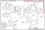
Here two diagrams one for 1000w and other 600w . but i have lots of confusion about this ckt.i got this ckt from docstoc.com


1. how to wind the transformer for both 600w and 1000w.
2. why cant use same thickness wire on primary and secondary.if possible what is the size of wire.
3. how to calculate the size of wire to be wind
4. whre we have to use dc capacitor.and ac capacitor
5. how to select toroid core transformer.can i get directly from market(in net he mentioned here in this ckt he used FT-37-77 AND HE MENTIONED IN you tube VEDIO not FT37-77 USE FT-140-77.
6. what is the difference between these two ft transformer.can i replace with that core transformer.

Please any one plesae help me................
 

Attachments

  • hhhh.png
    hhhh.png
    84.2 KB · Views: 426
  • ggggg.png
    ggggg.png
    144.1 KB · Views: 1,278
  • fgffff.png
    fgffff.png
    515.5 KB · Views: 520

2. The input voltage is 12 V, the output is 230V AC. The currents will be in the inverse ratio, so 300W at 12 V = 25 A, and at the output 230 V the current will be about 300/230 ~ 1.3 A. You need to use very thick wire for the 12V and there will not be enough room on the transformer to wind the secondary with this gauge wire. Its also a pain to wind with this thick wire.
3. Primary wire must be able to handle 25A without getting warm, so as the kit is handling 300W,the losses in the wire should be less then 1% total, so allow .5% for the primary and .5% for the secondary. So impedance of input circuit = 12/25 ~ .5 ohms so resistance of primary wire should be .5 X .005 ohms = 2.5 milli ohms. So work out the length of wire required for the primary and look up wire tables to select this length with a better then 2.5 milli ohm resistance, making sure it can handle 25 Amps. repeat same procedure for secondary.
Frank
 
Re: How to make this 1000w smps inverter ckt working

sir i am having above problem actualy in that 1000w circuit author used ferite toroid transformer ft 140-77 so i am confused about that.......
so tell me about this sir
 

140-77 refers just to the core of the transformer, with no windings. It looks like his transformers were wound by hand, and it's likely that you won't be able to find a suitable fully assembled toroidal transformer anywhere. You may want to look at non-toroidal E style transformers instead.
 

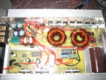
Looking at the schematic and the photo, there is one transformer in the schematic but two in the photo.
From my understanding you can't split the transformer into separate cores, so not sure if this is a separate issue?
 

That was not a center tapped transformer the circuit diagram and the image are same they are serially connected transformers according to the designer....
trans.JPG
There must be a enough distance between the cores to understand easily, they are different cores.........
So don worry doing the exact replica shd work...
 
Regarding my one or two transformers question, surely with two transformers the primary of the separate cores is going to ramp up the B/H magnetic curve and saturate? With the single core the average primary current is zero and saturation is not an issue.
 

sir i forgot to upload another 1000w circuit photo....now tellme sir how to wound the toroid transformer for that

https://obrazki.elektroda.pl/5511517500_1380385242.png

- - - Updated - - -

sir i forgot to upload another 1000w circuit photo....now tellme sir how to wound the toroid transformer for that

http://obrazki.elektroda.pl/5511517500_1380385242.png
 

I now understand with that circuit.

This circuit also answers your question.
Each toroid is wound 95 turns of 20 AWG for the secondary.
The primary is 2 windings of 5 turns and I believe each winding consists of 3 pieces of 13AWG wire which are wired in parallel. This is done to allow the wire to be of a size that can be formed round the toroid. Looking at the photo does show 'lots' of the thicker 5 turn wires.
You can check this against "chuckey's" earlier post for confirming power rating and also look up charts for the safe rating of 13 AWG wire.

- - - Updated - - -

Also looking at the original circuit this states:
Secondary 180 turns of 0.9mm wire.
Primary is 10 turns center tapped (or two coils of 5 turns connected as center tap) and each consists of 4 wires of 1mm copper.

From your earlier question "can I use the same wire?", if there is room on the toroid, I don't see why you cannot use 1mm for the secondary as well.

You still need to check the current rating of the wires to be sure of your design safety. From "chuckey's" post
"so 300W at 12 V = 25 A, and at the output 230 V the current will be about 300/230 ~ 1.3 A"
This shows the primary current is 25/1.3 times greater than output, i.e. 15 times. But this does not seem to be accounted for by the copper area of the input and output.
 
What battery/battery bank capacity you plan to use with this 600W or 1000W inverter ?

What working time and battery/battery bank life you expect ?


In bottom right corner of circuit diagram, you have author email address. Its best to hear him, because he try and test device.


Best regards,
Peter
 

sir can u explain how ic 4017 ,ic ka3525....555 timer, resistor ,capacitor inductor, mosfet transformer works.....detail.....please help me....i dont know how it works in this circuit
 

Here is a quick overview.
ic ka3525 is a high frequency oscillator that is driving the inverter at 48kHz. This makes the transformer core smaller compared to lower frequency operation.
So this part of the circuit is generating high DC voltage.

555 timer and R's and C are providing the reference frequency to get 50Hz out of the power converter.

ic 4017 is generating non-overlaping waveform to drive the power fets that are 'chopping' the high voltage DC to a 'squared off' power waveform.

So in summary left half of circuit is generating 340Vdc and right side is chopping this to 50Hz
 
what type of core size i have to use and where can i get that toroidal core transformer
 

Status
Not open for further replies.

Similar threads

Part and Inventory Search

Welcome to EDABoard.com

Sponsor

Back
Top