Continue to Site

Welcome to EDAboard.com

Welcome to our site! EDAboard.com is an international Electronics Discussion Forum focused on EDA software, circuits, schematics, books, theory, papers, asic, pld, 8051, DSP, Network, RF, Analog Design, PCB, Service Manuals... and a whole lot more! To participate you need to register. Registration is free. Click here to register now.

ESR of Electrolytic capacitors with same value and different voltage rating

Status
Not open for further replies.

manishanand14

Full Member level 4
Full Member level 4
Joined
Sep 3, 2011
Messages
203
Helped
10
Reputation
20
Reaction score
9
Trophy points
1,308
Location
Bangalore ,India
Activity points
2,572
Hello Everyone

Please tell me which capacitor has higher ESR: 1000uF/16V or 1000uF/63V and why?
 

You can not tell that. Look up the datasheet for both brands or types (ifthey are not the same brand or typer)
The datasheet will give you D, the dissipation factor. D x Xc = ESR at the given frequency. Most times 1 kHz or 100/120 Hz. Often you also find the impedance at 100kHz. Impedance is not ESR.
Impedance is |Z| and Z = (R - jX) R=ESR=resistance, -jX is the reactance
https://www.pa4tim.nl/?p=3775 I wrote a page about ESR
 

according to these tables : **broken link removed**

esr is higher at lower voltages
but I'm not as qualified to explain why !
regards,
 

The tables are wrong, but the graph is correct in the above post. ESR goes up with higher voltage rated capacitors. Fortunately however a higher voltage capacitor is larger in size that more than offsets the increased power dissipation caused by the increased ESR.
One of the causes of ESR is the condition of the dialectric and a higher voltage capacitor has a thicker dialectric which causes the higher ESR.

The ESR of a capacitor is more or less constant at frequencies between 0 and 150Khz, above 150Khz the ESR goes down untill you get to between 1-2 Mhz when the inductance of the capacitor becomes important.
 
OMG I didnt realize that the table and the graph on the site are the exact opposite !!!!!!
 

ESR goes up with higher voltage rated capacitors. Fortunately however a higher voltage capacitor is larger in size that more than offsets the increased power dissipation caused by the increased ESR.
One of the causes of ESR is the condition of the dialectric and a higher voltage capacitor has a thicker dialectric which causes the higher ESR.
There's probably an error of reasoning involved because thicker dielectric will be already compensated by larger effective area. The ESR is however not located in the Al2O3 dielectricum itself rather than adjacent conductive layers. How it's thickness and conductivity varies with rated voltage depends.

All in all, it's difficult to derive a simple rule. You'll find many electrolytic capacitor series where ESR is decreasing with increasing voltage and constant capacitance.
 

There's probably an error of reasoning involved because thicker dielectric will be already compensated by larger effective area

The larger area probably offsets some of the effect of a thicker dieletric, but not all maybe. Another factor maybe the increase in foil length, I suppose it all depends if the height to width ratio for this. I base my observations on measuring the ESR of many hundreds of different type of capacitors when I designed a ESR meter, and I found that the dialetric type and condition makes the largest change of ESR
 

ESR is not even a bit flat between 0 and 150 KHz.. Besides that, it is depending on the size of the cap. A big cap will reach it's SRF far before 1MHz,. And a low ESR 10V cap from brand X can have a much higer ESR as a 100V cap from brand Y. Low ESR is not defined. If the best cap you produce has a dreadfull ESR you are still alowed to call it a low ESR cap. I have seen chinese junk low ESR caps with a much higher ESR as standard caps from a brand like Panasonic.

I too designed some ESR meters, and measured hundereds of cap using GR (including the GR-1620) , ESI , Marconi and HP bridges , A IET DE-5000 and things like VNA's other impedance meters. I collect bad caps that I measure and mount on test pcbs to test meters. ESR is in the MOhms at DC, then drops fast until 1 to 5 KHz. Then it drops a bit lower to reach the lowest value around 50-100 kHz (for bigger can sooner as for smal smd caps, and thie lowest value is not at the SRF) The cause is the dielectroic loss and the increasing skin effect. The SRF is caused by the increasing ESL Bigger caps, longer legs cause more skin effect and ESL and lower SRF
 

ESR is not even a bit flat between 0 and 150 KHz..

pjmelect probably shouldn't have specified a span from 0 Hz to 150 kHz. No manufacturer specifies ESR down to 0 Hz. In fact, the usual ESR curves only go down to 50 Hz or 100 Hz:

**broken link removed**

But, the ESR of aluminum electrolytics is typically quite flat from 50 Hz up to the SRF (and sometimes beyond). For example, here is a sweep showing impedance (Z) and ESR (Rs) of an aluminum electrolytic from 50 Hz to 5 MHz; the ESR is quite flat up to 100 kHz:

attachment.php


Contrary to what pjmelect says, the ESR for this cap doesn't go down above 150 kHz, so his assertion is not true for all electrolytics.

Besides that, it is depending on the size of the cap. A big cap will reach it's SRF far before 1MHz,. And a low ESR 10V cap from brand X can have a much higer ESR as a 100V cap from brand Y. Low ESR is not defined. If the best cap you produce has a dreadfull ESR you are still alowed to call it a low ESR cap. I have seen chinese junk low ESR caps with a much higher ESR as standard caps from a brand like Panasonic.

This is all quite so, and as you said in your previous post, the only fair comparison would be between caps made by the same manufacturer, and in the same series from that manufacturer. That said, it's generally true that higher voltage caps have higher ESR, all other things being equal.

I too designed some ESR meters, and measured hundereds of cap using GR (including the GR-1620) , ESI , Marconi and HP bridges , A IET DE-5000 and things like VNA's other impedance meters. I collect bad caps that I measure and mount on test pcbs to test meters. ESR is in the MOhms at DC, then drops fast until 1 to 5 KHz. Then it drops a bit lower to reach the lowest value around 50-100 kHz (for bigger can sooner as for smal smd caps, and thie lowest value is not at the SRF) The cause is the dielectroic loss and the increasing skin effect. The SRF is caused by the increasing ESL Bigger caps, longer legs cause more skin effect and ESL and lower SRF

The SRF isn't caused by increasing ESL; the ESL isn't increasing. The SRF is caused by the increasing reactance (with increasing frequency) of the ESL
 

Attachments

  • 130820084021.bmp
    247.7 KB · Views: 767

You are right about the ESL. That is indeed the correct description.

I do not complete agree with the flat ESR and lowest ESR at SRF. The latter is "old school" theory. Today using VNA's it is proven that ESR is not at a minimum on the SRF. I have read several publications about that. I was looking for that because I found out using my VNA that the ESR was often lower before SRF (self resonant frequency, in case of caps sometimes called series resonant frequency). The reason they thought ESR was at minumum at SRF is because they used to measure caps using an impedance analysers that only measured |Z| and were not able to split this into R and jX. Most VNAs are not able to measure at low frequencys. But with the very small smd caps and much higher frequencys today the VNA is used more often because many impedance meters are limmited to a few MHz. However the difference is very small and very hard to measure. A very small calibration mistake can shift the SRF to a complete other frequency. I use custom traces, de-embedding, OSLC calibration and custom made fixtures with calkits for these measurements. Very interesting things. I also measured on thinngs like skin effects, dielectrics behaviour and leakage, fringing fields (if that is the correct english term for edge effect) etc

About the flat ESR, it is not important, the graphs show it and people can see it. But for those who do not are experienced in reading analyser graphs and if we keep it correct, I have to add that you use a log scale. My experience is it is getting flat somewhere between 10-50kHz. On linear VNA plots the picture looks complete different but it is the same. The reason it looks flatter in your plot is because you use a log sweep. Make a linear sweep and you will see it better. Pease has showed that about the forward diode voltage. He made a log/log graph for the knee Voltage and that gave a straight line in the graph. So it looked like a linear behavour but it was just an example to show how to read graphs.
This is not a negative comment, I know from EEV blog you know a lot about caps but just to make it complete. (I have 3 VNA's and they are also usable as impedance meters, 1 of my VNAs is able to operate from 10Hz-1400 MHz, the other from 1 kHz to 1300 MHz, the 3rd from 100 kHz to 100 MHz. My bridges (GR1620, 1650, 1608, 1603 operate from 20Hz to 20kHz, I also haver a IET DE-5000, HP4260 ESI 277 and I have some home made meters like a fF meter and some ESR meters (with adjustable frequency from 10kHz-100kHz))
I'm very interested in (paracitic and extreme) measurements on components (so things like uOhm or POhm, ESR, ESL, noise, capacitance or inductance of resistors etc) I have a lot of gear in that area, so caps are interesting components for me..
 
  • Like
Reactions: FvM

    FvM

    Points: 2
    Helpful Answer Positive Rating
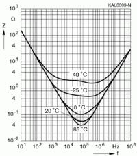
A point that should be considered in addition is the strong temperature dependency of ESR, as illustrated in the below diagram from an Epcos application note. Although the diagram doesn't distinguish between real and imaginary impedance components, it's almost obvious what is ESR, because C and L are effectively constant. The fact questions the purpose of exact ESR measurements for electrolytic capacitors in my view. Type variations and aging have to be added, so you'll usually end up with an estimation of maximum/minimum ESR for a particular application and related operation conditions.


ESR of foil capacitors is a much more predictable and reliable thing, and an important parameter for some power electronic applications, e.g. resonant converters.
 

I do not complete agree with the flat ESR and lowest ESR at SRF.
It's not a matter of agreeing or not agreeing. One only need make a series of measurements to find out what the facts are.

I made no assertions about whether or not the lowest ESR occurs at the SRF. Measurements show that sometimes the lowest ESR does occur at the SRF, and sometimes it doesn't. One can't really say one way or the other; it depends on the particular capacitor.

Also, it's not possible to accurately make a general statement about the flatness of the ESR with frequency below 100 kHz. For some capacitors, the curve is quite flat, for other capacitors it's not.

Here's a sweep of an aluminum electrolytic where the minimum ESR does not occur at the SRF. This capacitor also has an ESR curve which is not at all flat with frequency:

attachment.php


Here's a sweep of another capacitor where the minimum IS at the SRF:

attachment.php


Today using VNA's it is proven that ESR is not at a minimum on the SRF.

This is a very general statement which I don't find to be true for all capacitors.

Using Impedance Analyzers, it is proven that ESR (of aluminum electrolytics) sometimes IS a minimum, sometimes IS NOT a minimum at the SRF. I gave examples above.

I have read several publications about that. I was looking for that because I found out using my VNA that the ESR was often lower before SRF (self resonant frequency, in case of caps sometimes called series resonant frequency). The reason they thought ESR was at minumum at SRF is because they used to measure caps using an impedance analysers that only measured |Z| and were not able to split this into R and jX.

I don't know who you're referring to when you say "they", but impedance analyzers that can separate the real and imaginary parts of an impedance have been available for more than 30 years, and bridges that can do that have been available for much more than that. Whose publication did you read that claimed that the minimum ESR occurred at the SRF? Obviously, they didn't do a good job of researching the facts. I have never thought that was the case.

Most VNAs are not able to measure at low frequencys. But with the very small smd caps and much higher frequencys today the VNA is used more often because many impedance meters are limmited to a few MHz. However the difference is very small and very hard to measure. A very small calibration mistake can shift the SRF to a complete other frequency. I use custom traces, de-embedding, OSLC calibration and custom made fixtures with calkits for these measurements. Very interesting things. I also measured on thinngs like skin effects, dielectrics behaviour and leakage, fringing fields (if that is the correct english term for edge effect) etc

This thread is about electrolytic capacitors, and hardly anyone expects good performance from an electrolytic at high RF frequencies, especially if the capacitor is an electrolytic with wire leads.

I don't agree that VNAs are used more often for component measurement; they are usually used in a controlled impedance environment. They don't work as well for measuring the impedance of components that may have an impedance much different from 50 or 75 ohms. There aren't a lot of impedance analyzers available in the world, but the modern ones aren't typically limited to a few MHz. For example:

http://www.home.agilent.com/en/pd-1...-to-110-mhz?nid=-33831.536879654&cc=US&lc=eng

and:

http://www.home.agilent.com/en/pd-1...al-analyzer?nid=-33831.536880679&cc=US&lc=eng

But what's the point in measuring an aluminum electrolytic much above a few MHz anyway? If I'm measuring a leaded electrolytic, I just set the analyzer to only sweep up to a few MHz.

The fixtures that come with these impedance analyzers are designed to be usable over the frequency range of the instrument, and it's not hard to "de-embed" the fixture parasitics. But when measuring components with wire leads, the slightest additional length of lead not inserted in the fixture will complete dominate any small calibration mistake anyway.

About the flat ESR, it is not important, the graphs show it and people can see it. But for those who do not are experienced in reading analyser graphs and if we keep it correct, I have to add that you use a log scale. My experience is it is getting flat somewhere between 10-50kHz. On linear VNA plots the picture looks complete different but it is the same. The reason it looks flatter in your plot is because you use a log sweep. Make a linear sweep and you will see it better.

When making measurements where the frequency range of the measurements and the variation of the measured parameters extend over many orders of magnitude, it is customary to use logarithmic scales.

The ESR plots provided by manufacturers are always (as far as I have seen) shown with logarithmic scales. If we want to easily compare measurements with the curves provided by the manufacturers, it makes sense to plot the data in the same way that the manufacturers do.

I'm not saying that the ESR curve is absolutely flat, but you said that it's "...not even a bit flat." You were, of course, referring to pjmelect's unfortunate choice of a frequency range that went all the way down to zero hertz. It's quite true that the curve is not even approximately flat over that range, but it is reasonably flat for some electrolytics if the sweep only goes down to 50 Hz. I show an example above where it is NOT even reasonably flat when the sweep starts at 50 Hz, and in the other post where it IS reasonably flat.

I see descriptions of capacitor ESR and D behavior that are claimed to be universal. The descriptions are not limited to one type of capacitor, such as electrolytic, or film, or ceramic. It is said that some parameter is flat with freaquency, or is NOT flat with frequency. I find that if a large number of capacitors are measured, the assertions are found to be not universally true. For some capacitors it may be true, and for others it is not true.
 

Attachments

  • 130820220530.bmp
    247.7 KB · Views: 564
  • 130820220555.bmp
    247.7 KB · Views: 575

Should we care about capacitor ESR above SRF, in other words when the capacitor isn't working as a capacitor any more? Usually we don't.
 

If high frequency currents are flowing in the capacitor at any frequency, those currents will cause heating due to the I2R losses. Whether we care or not will depend on the magnitude of those losses, and how they fit into the thermal budget. We might still need a low ESR above the SRF.
 

I'm not saying that the ESR curve is absolutely flat, but you said that it's "...not even a bit flat." You were, of course, referring to pjmelect's unfortunate choice of a frequency range that went all the way down to zero hertz. It's quite true that the curve is not even approximately flat over that range, but it is reasonably flat for some electrolytics if the sweep only goes down to 50 Hz. I show an example above where it is NOT even reasonably flat when the sweep starts at 50 Hz, and in the other post where it IS reasonably flat.

When I was designing my ESR meter I wanted to know what effect that frequency would have on the measurement of the ESR, I do not have access to any fancy equipment so I had to measure the ESR with a signal generator and series resistor along with a little bit of maths. I only tried a few capacitors which gave similar results, I tried 10hz as my lowest frequency and on the resulting graph I naturally extended the line to zero. I found that the ESR was essentially flat from my lowest measurement to around 150Khz within the measurement accuracy of my setup, which admittedly was not that great, above this frequency the ESR reduced significantly up to 1-2Mhz where the inductance of the capacitor started causing strange effects. I was using square waves to do this as that is what my ESR meter used, but I did try sine waves, which made little difference to the ESR.
 

What was the principle of operation of your ESR meter? Kripton2035 lists a lot of designs:

**broken link removed**

Can you find your mode of operation among those? If so, can you provide a link to the one similar to what you did?
 

The ESR meter I designed was simply a micro controlled version of my bench lash up of a 4.7R resistor in series with the capacitor under test with the square wave generation and the measurement, calculation and display done by a PIC micro. I built it as a tool to help me fault find power supplies. It measures the ESR and is a good low resistance meter. It only puts 100mV across the capacitor under test so that you can measure the ESR of the capacitor in circuit. I chose a frequency of 70Khz so that a 0.1uF capacitor in parallel with the capacitor under tests low ESR would not mask the ESR of the electrolytic under test. Although it works well as a ESR meter I am still trying to figure a better way to measure the capacitance of the capacitor as well as the ESR as I currently measure the reactance of the capacitor at different frequencies, which is a poor way to measure a capacitors value particularly if it has high ESR.
 

Status
Not open for further replies.

Part and Inventory Search

Welcome to EDABoard.com

Sponsor

Back
Top