Continue to Site

Welcome to EDAboard.com

Welcome to our site! EDAboard.com is an international Electronics Discussion Forum focused on EDA software, circuits, schematics, books, theory, papers, asic, pld, 8051, DSP, Network, RF, Analog Design, PCB, Service Manuals... and a whole lot more! To participate you need to register. Registration is free. Click here to register now.

[SOLVED] Measuring Inductivity

Status
Not open for further replies.

chiques

Full Member level 3
Full Member level 3
Joined
Nov 21, 2007
Messages
170
Helped
2
Reputation
4
Reaction score
2
Trophy points
1,298
Location
California
Activity points
2,556
How can I measure the inductivity of an antenna operating at 2.45 GHz using a VNA?
 

The correct term is inductance. Any antenna at 2.45 GHz has a complex impedance which can be measured as S11 by a VNA, referenced to e.g. 50 Ohms. To measure antenna impedance, you should make sure that the antenna under test is located in a "free space", far from other objects, or, inside of an anechoic chamber.
 

jiripolivka is correct. You invented your new noun. If it gets popular, you will have contributed to the language :)

Once you have the Real and Complex components of the antenna impedance, as measured by the VNA (R+jX), the value of X in Ohms is the amount due to the inductive component. The actual inductance value is found by knowing X = 2*pi*Freq*X

So - get the value and divide by 2*pi*Freq. Take care with the units. If Freq is Hz, then Inductance is in Henrys. If Freq is in GHz, then inductance is in nH. Maybe even the VNA has the facility to directly display the inductance. Keep in mind that the inductive (and capacitive) energy storage in an antenna near field is not quite the same as having an inductor as a lumped component. It is the equivalent inductance that the antenna structure behaves as if were there.
 

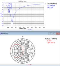
I guess I am still a bit confused. i have the following resonance. Not sure how to find the inductance of this system?


I guess I am still a bit confused. i have the following resonance. Not sure how to find the inductance of this system?


A resonance happens only when a capacitance and inductance are connected in series or in parallel.

Your case looks like a series resonance at 102 MHz. You must find both parts, L and C. Smith chart center indicates no resonance a perfect impedance match (to 50 Ohms).
 

A resonance happens only when a capacitance and inductance are connected in series or in parallel.

Your case looks like a series resonance at 102 MHz. You must find both parts, L and C. Smith chart center indicates no resonance a perfect impedance match (to 50 Ohms).

Sorry about that. I was fiddling around with the tuning. Here is my 2.45 circuit. The fact that my S11 has such a low return loss and my smith chart is fairly well centered at 50 Ohms still does not qualify my circuit as "resonant" at 2.45 GHz?:shock:

Is this a case where 1/(2*pi*f*C)=2*pi*f*L ?
 

Attachments

  • 2.45_PCB_ANTENNA.pdf
    64.9 KB · Views: 104

Sorry about that. I was fiddling around with the tuning. Here is my 2.45 circuit. The fact that my S11 has such a low return loss and my smith chart is fairly well centered at 50 Ohms still does not qualify my circuit as "resonant" at 2.45 GHz?:shock:

Is this a case where 1/(2*pi*f*C)=2*pi*f*L ?

Yes, it is.
 

So 'C' and 'L' can be arbitrary? Basically you can lower one and increase the other???
 

OK - you nearly have it. Go down this route a little.

If you had a pure inductance, then the Smith chart trace would have gone clockwise around the chart rim.
Instead, it came into the chart, making a circle of it's own, which at one point, visited the centre, where it becomes resistive.

In a series resonant circuit, the impedance is jωL + Xc where Xc=1/jωC.
Using j^2=-1, Xc will become Xc=-j/ωC
Impedance becomes Z = jωL -J/ωC.

At resonance, Z becomes zero as ωL becomes equal to 1/ωC where the inductance and capacitance cancel each other out. Therefore, at resonance, you have no information to let you get at the inductance. You see a resistive near short-circuit, with nearly zero reactive component. (0.57-j84.35e-6)

BUT, if you put a few markers at other frequencies on that Smith curve, and readoff the impedances, any two of them would allow you to solve for the inductance and capacitive parts of that circuit.
 

Your case looks like a series resonance at 102 MHz.
Is it so? Impedance is converging to short circuit (s11 = -1) for high and low frequencies, so it rather looks like parallel resonance, I think.
 
Last edited:

Fvm - you are right!
At first I did not know if it was a series LC set between two ports, or a parallel tuned circuit place across the termination.
As it happens, the earlier PDF posted in this thread shows a parallel tuned circuit.
 

Out of curiosity: Why would it make a difference between a series or parallel resonant circuit?
 

Out of curiosity: Why would it make a difference between a series or parallel resonant circuit?

An LC parallel (tank) circuit generally has minimal ohmic resistance in the loop. It can have high Q and low damping.

A series LC usually has some ohmic resistance in the picture, which reduces Q and reduces its quickness to resonate.

So 'C' and 'L' can be arbitrary? Basically you can lower one and increase the other???

The capacitor cannot be made too large, because it will need more current to charge and discharge. Any substantial series resistance could hinder that.

Likewise the inductor cannot be made too small, because a small Henry value is associated with high current.

If available current is small, then consider making the inductor large, and the capacitor small. A ratio between 100 and 10,000 is typical.
 
  • Like
Reactions: chiques

    chiques

    Points: 2
    Helpful Answer Positive Rating
OK - there are several ways to wire it up.
1) A series LC between ports. At resonance, S11 approaches match in the centre of the chart.
2) A parallel tank circuit between ports. At resonance, S11 goes open
3) A series LC strapped right across 2 ports. S21 goes low at resonance, as the network is shorted
4) A parallel LC tank across the 2 ports. It shorts the network everywhere except resonance.
This is the one shown in the PDF of the sixth posting. S11 becomes beautiful at resonance.
Port1 is 50 Ohms, and I think R1 being 0.051kΩ is a 50 Ohm termination in place of port 2.

In all this, going after figuring L when it has a C with it, and the C is known, only requires finding the resonant frequency.
Then L=1/[(ω^2)*C] or L = 1/[4*pi^2*f^2*C].

This is the simplest and best way, but requires we already know C. I only noticed C was 20pF a bit later.
Without knowing C, in a real measurement, I guess the way is to use two frequencies.
 
  • Like
Reactions: chiques

    chiques

    Points: 2
    Helpful Answer Positive Rating
Status
Not open for further replies.

Part and Inventory Search

Welcome to EDABoard.com

Sponsor

Back
Top