Continue to Site

Welcome to EDAboard.com

Welcome to our site! EDAboard.com is an international Electronics Discussion Forum focused on EDA software, circuits, schematics, books, theory, papers, asic, pld, 8051, DSP, Network, RF, Analog Design, PCB, Service Manuals... and a whole lot more! To participate you need to register. Registration is free. Click here to register now.

Driving MOSFET FROM PIC

Status
Not open for further replies.

Korawy

Member level 3
Member level 3
Joined
Sep 8, 2011
Messages
61
Helped
1
Reputation
2
Reaction score
1
Trophy points
1,288
Visit site
Activity points
1,776
Hi all..

I have a problem driving a MOSFET From PIC, for the purpose of PWM, I know that there are Logic MOSFETs but the one i have now is IRF540.
I tried to drive it directly from the PIC it rotates well but the problem in the encoder readings, So i need to know a circuit to drive the IRF540 mosfet from the pic..

Thanks,,,
 

Heya Korawy,

The article at **broken link removed** describes driving MOSFET's from logic in considerable detail. I've used the (simple) BJT configuration shown in Fig. 10 on numerous occasions with success using complementary pairs such as the BC337 & 327. Try Rgate = 10R and Rb ~100R (depending on your transistors).
 
  • Like
Reactions: Korawy

    Korawy

    Points: 2
    Helpful Answer Positive Rating
Heya Korawy,

The article at **broken link removed** describes driving MOSFET's from logic in considerable detail. I've used the (simple) BJT configuration shown in Fig. 10 on numerous occasions with success using complementary pairs such as the BC337 & 327. Try Rgate = 10R and Rb ~100R (depending on your transistors).

Thanks thylacine1975...

i downloaded the file and look at fig 10, and found this "Of course, they can be and should be placed right next to the power MOSFET they are driving." I cant do this as i have already built the PCB circuit, Is it a big problem.

I will build the circuit but with 2n3904 & 2n3906 transistors what should be the resistor and the bypass capacitors values?

Thanks again ,,, :)
 

The "seriousness" of the effect of some distance between the buffer transistors and your MOSFET is going to be largely a function of MOSFET switching current and dI/dt. I'm going to go out on a limb (and knowing nothing about your circuit) and say it'll probably be fine - especially since you mention that the motor (load) already seems to be doing something sensible (and presumably your micro hasn't crashed/gone into latchup etc etc :)

Having said that, if you're going to be retrospectively adding bits to your PCB - you might as well place the buffer transistors up against the MOSFET, especially since Vdrv can/should be the load's supply (=12?) voltage.

For the decoupling capacitors 100nF will be fine, since this will be much larger than the MOSFET gate capacitance (and thus guaranteed to be good "local charge reservoirs").
The 3904/3906 don't quite have the current rating of the 337/327 pair, so I'd expect you'd be able to increase Rb to ~470R without problem.

Cheers :)

- - - Updated - - -

The "seriousness" of the effect of some distance between the buffer transistors and your MOSFET is going to be largely a function of MOSFET switching current and dI/dt. I'm going to go out on a limb (and knowing nothing about your circuit) and say it'll probably be fine - especially since you mention that the motor (load) already seems to be doing something sensible (and presumably your micro hasn't crashed/gone into latchup etc etc :)

Having said that, if you're going to be retrospectively adding bits to your PCB - you might as well place the buffer transistors up against the MOSFET, especially since Vdrv can/should be the load's supply (=12?) voltage.

For the decoupling capacitors 100nF will be fine, since this will be much larger than the MOSFET gate capacitance (and thus guaranteed to be good "local charge reservoirs").
The 3904/3906 don't quite have the current rating of the 337/327 pair, so I'd expect you'd be able to increase Rb to ~470R without problem.

Cheers :)
 
  • Like
Reactions: Korawy

    Korawy

    Points: 2
    Helpful Answer Positive Rating
thanks thylacine1975 ,,,

Making Modifications to the PCB, so that adding the buffer transistors against the MOSFETs is impossible, but i can make another modification, I will take the MOSFET away from the PCB and put it in the PCB where the driver exists, but this will lead to a long drain line.

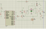
This is the circuit..

Untitled123.png

The PCB that i have done is the relays, transistors and the mosfet only.
I can take away the mosfet and put it in the pic board (which is breadboard).

Regards.. :)
 

Although long lines connected to any port of a MOSFET are generally undesirable, a long drain connection is probably the lesser of the evils...
What sort of drain (motor) current is the FET switching? Unless you're pushing the FET to it's rated maximum of 30+ amps, I suspect it'll be fine :)
 

I tried the circuit but it doesnt work properly, the motor worked strangely, and the light of the LCD became weaker, although the encoder readings seem to be right, and this done only when powering up the relay....?!
 
Last edited:

Long Drain Line is not applicable cause it depends on current, But the Gate depends on the volt...
I returned back the MOSFET, and made a long Gate Line, it works properly till now...

Thanks anyway thylacine :)
 

I have a problem with the PDF, the link you provided what is the meaning of (RHI) PAGE 8 as i want to calculate the power dissiupate on the mosfet,power switching losst etc...
pls need help
 

Status
Not open for further replies.

Similar threads

Part and Inventory Search

Welcome to EDABoard.com

Sponsor

Back
Top