Continue to Site

Welcome to EDAboard.com

Welcome to our site! EDAboard.com is an international Electronics Discussion Forum focused on EDA software, circuits, schematics, books, theory, papers, asic, pld, 8051, DSP, Network, RF, Analog Design, PCB, Service Manuals... and a whole lot more! To participate you need to register. Registration is free. Click here to register now.

Decopling capacitors value selection

Status
Not open for further replies.

shaswat

Advanced Member level 4
Full Member level 1
Joined
Jul 2, 2013
Messages
115
Helped
1
Reputation
2
Reaction score
1
Trophy points
18
Activity points
963
During the designing of a circuit how do we know where to add decoupling capacitors?How to calculate these values
 

During the designing of a circuit how do we know where to add decoupling capacitors?How to calculate these values

Generally decoupling caps are needed for two things:
- to keep high frequency currents from flowing over the PCB tracks to the supply (causing EMC problems by radiation and injecting noise on the supply of other circuits/chips)
- to short-circuit noise on the supply of sensitive circuits

Therefore, you need to put capacitors as near as possible to the supply of circuits that generate noise and circuits that are susceptible to it.
Generally, 100nF ceramic SMD caps (these have the best high-frequency behaviour) are placed as close as possible to the VSS/VDD pins of a chip
One larger value Elco can be placed near the supply, or near to circuits that generate low-frequency currents.
The value of this depends on the LF-current that is drawn and the output impedance of the supply, but usually 100uF will be enough.

Have a look at: https://www.learnemc.com/tutorials/Decoupling/decoupling01.html
 

100 nF is a standard value or we can select any value from 0.1uF to 0.01 uF??

- - - Updated - - -

100 nF is a standard value or we can select any value from 0.1uF to 0.01 uF? In some circuit,it uses 100nF in the input and 0.1uF at the output of the IC? So is it necessary to select only 0.1 uF at the output ?What happens when i change it to 1uF?

The reason that 100nF is more or less the standard value for high frequency decoupling is that higher values start to behave worse at high frequencies: the parasitic series inductance increases, which reduces the impedance at high frequencies, so high frequency noise is less efficiently short-circuited.
Using a lower value also reduces the effect of the capacitor:

Have a look at figure 8-11 in:
https://www.google.be/url?sa=t&rct=...9ozXzfzdsSegWzdzwZ91u9Q&bvm=bv.48705608,d.ZWU
 
A decoupling capacitance can also be thought of as a small current supply at the point of load.

When a device's power pin needs a fast transient current, the decoupling caps should supply it. Otherwise, it will try to come through the inductance of the power/ground conductors and a voltage spike will be induced. V = L di/dt.

You can usually easily calculate the minimum required decoupling capacitance, for simple devices like amplifiers, or look at the datasheet for other types of devices, or use knowledge of the device and its load.

You need to know how much current might be required, in what length of time. Often, if you know what the output current can do, and how fast it should do it, then you can assume that the power pin has to be able to supply that current.

You also need to know how much you are allowed to let the power rail voltage change, when the current is supplied. It will sag when current is drawn from the capacitors and it will spike from the current coming through the rail inductance.

Use the capacitor equation:

i = C ∙ dv/dt

but use an approximate linear form of that, solved for C:

C ≥ (1/2)Δi ∙ Δt / Δv

Or, with capacitor ESR:

C ≥ ((1/2)Δi ∙ Δt) / (Δv - (Δi ∙ ESR))

Remember that C is in Farads. If you want the answer in microFarads, multiply the right side by 1000000.

Example:

If the worst-case transient current is 10 Amps in 1 us and we want the rail voltage to change by no more than 1 Volt, then we have:

C ≥ (1/2)10 ∙ 0.000001 / (1 - (10 ∙ ESR))

At this point, we can see that ESR must be much less than Δv/Δi !! The higher the ESR is, and the closer to Δv/Δi it is, the more excessive the capacitance requirement becomes. If calculating an electrolytic's capacitance, here, it is useful to first re-solve the equation using an approximation for the ESR, i.e. ESR = 0.02 / (C ∙ Capacitor_Voltage_Rating).

For the example, if we assume that the ESR = 0.01 Ohm, we get C ≥ 5.56 uF.

But if the ESR was 0.09 Ohm, the required capacitance would be ≥ 50 uF!


METHOD 2:

You could also do the same thing in a different-looking (but actually equivalent) way:

If you know the rise time of the current that the power pin might require, then you can use the following:

Choose the maximum change in rail voltage, Δv, that you can tolerate for the maximum-possible transient change of the supplied current, Δi.

That gives you a "target impedance":

Ztarget = Δv/Δi

Since the magnitude of the impedance of a capacitance is Z = 1 / (2 π f C), we can solve for C for a given Z (Ohms) and frequency f as:

C = 1 / (2 π f Z)

The frequency that is equivalent to an example rise time of 1 us is:

f = 1 / ( π ∙ trise )

f = 318 kHz

So we must stay within our target impedance limit up to at least 318 kHz, to be able to not have a rail voltage disturbance greater than Δv for any Δi.

We can calculate that in order to maintain our target impedance of Δv/Δi, we would need a total capacitance of at least

C >= 1 / (2 ∙ π ∙ f ∙ Δv/Δi)

For example, if we want to be able to draw 10 Amps in 1 us and not have the rail voltage sag by more than 1 Volt:

= 1 / (2 ∙ 3.14 ∙ 318000 ∙ (1/10))

= 5 uF or more would be required.

Note that the capacitor ESR was not accounted for, in this example. But the ESR must be much less than the target impedance!


FOR HIGHER FREQUENCIES:

For higher frequencies (i.e. faster slew rates, not repetition rates), you must find the maximum inductance that can be tolerated, in the decoupling network. This will basically tell you the maximum allowable LENGTH of the decoupling capacitors' round-trip connections, including the cap's lead spacing.

I don't have time to go into a lot of detail and would have to re-derive the equations. What I will show is not going to be totally accurate, since it won't account for all of the impedance components. But it will give you the basic idea. Anyway, once you get to high frequencies, you might as well use some expensive electromagnetic simulation/solver software, if you want to try to make everything optimal (or even just functional).

For an inductance,

V = L di/dt

So the maximum decoupling inductance we can tolerate would be:

L ≤ Δt ∙ Δv / Δi

Our previous example was NOT "high frequency". In that case, with 10 Amps in 1 us and less than 1 V rail disturbance, we would get

L ≤ 0.1 uH

But if we wanted 1 Amp in 0.1 us with no more than 0.1 Volt delta (still easy), we'd get

L ≤ 10 nH

If the common estimate of PCB trace self-inductance is used, which is 1 nH per mm, we could have 10 mm round trip, including the capacitor's lead spacing.

What will happen, for almost any more-stringent case, is that the maximum allowable inductance will not be achievable with ANY capacitor's lead spacing, not to mention trace lengths. In that case, you have to start using multiple capacitors in parallel. Theoretically, the inductance and ESR will be divided by the number of capacitors placed in parallel. BUT, if there is any mutual inductance, it partially wrecks the algebra for the inductance reduction and you won't achieve the 1/ncaps factor. It will help to place the caps such that their currents do not share the same conductor. At this point, of course, you would be using a multilayer PCB, with separate planes for power and ground, etc., and you wouldn't be able to do the proper calculations by hand.

Bypassing is also needed, in many cases. For most amplifier chips, and transistor amplifier circuits, there is a hidden high-frequency positive feedback loop through the power supply rail and a bypass cap is needed to short-circuit the high frequencies from rail to ground, to prevent HF instability or marginal stability (oscillation or ringing). Use a physically-small cap, placed within 2 mm of the power pin, with the shortest-possible connection to the load or device ground.

Here is a link to a paper that is pretty good, and has the right equations, but might be overkill for most DIYers:

http://www.si-list.net/files/published/sun/cpmt_1999.pdf

That paper was mentioned here:

http://www.sigcon.com/Pubs/news/1_6.htm

And here is a real treasure trove of design information (except they call them bypass caps instead of decoupling caps):

**broken link removed** capacitors

Cheers,

Tom
 
Last edited:
Thnxx for such a great and beautiful explanation......+10 for the patience you showed during writing such a large explanation.........
 

Decoupling capacitor values depend on the frequency of the circuit. In RF circuits you might use 100pF or less, with some larger values in parallel. For analog instrumentation I have sometimes found improvements using 100uF compared to 10uF, but that is where the circuit is working with very low frequencies.

Keith
 

A decoupling capacitance can also be thought of as a small current supply at the point of load.

Somebody told me the above explanation. I have some doubt on this comment. I think decoupling is responsible for the filtering and in case output is not smooth, there would be small dips at the output. Due to this,is there is variation or dip in the current (I am not sure correct me if I am not)
 

Decoupling capacitor values depend on the frequency of the circuit. In RF circuits you might use 100pF or less, with some larger values in parallel. For analog instrumentation I have sometimes found improvements using 100uF compared to 10uF, but that is where the circuit is working with very low frequencies.

Keith

That is certainly correct. And for low frequencies, we can lump the decoupling and power supply reservoir capacitances together, when calculating the minimum requirement. With a linear supply with transformer, rectifier, and reservoir capacitance, we can set the Δt that I mentioned to 1 / (2 fmains), the charging period, as a worst case. Then it also becomes clear that lower frequencies require more capacitance.

For an amplifier, it is safest to assume that the output might be DC at the maximum peak level that a sine might have, according to the rated maximum RMS output power. And Δv, the max allowable peak-to-peak ripple voltage, can be determined, because we know the peak Vrail_max, and the peak output voltage (according to max rated output power), and the clipping voltage (minimum voltage between amplifier power input and amplifier output, often Vceo + the voltage across a low-value emitter resistor; usually 2 to 5 volts total). So Δv_max = Vrail - Vclip - Vout_peak. We also know the max current, i, since we know Vout_peak and the load resistance. Then we can calculate the minimum C required.

- - - Updated - - -

A decoupling capacitance can also be thought of as a small current supply at the point of load.

Somebody told me the above explanation. I have some doubt on this comment. I think decoupling is responsible for the filtering and in case output is not smooth, there would be small dips at the output. Due to this,is there is variation or dip in the current (I am not sure correct me if I am not)

When voltage at the power pin of the device drops even slightly, the decoupling cap releases current, to try to meet the demand.
 

There are 2 reasons for a capacitor in this case.

1. to suppress 'noise' on the supply lines

2. to add stability or smoothing of the voltage

A large value cap is poor at suppressing noise, so if you want both [suppression and stability] you need both a high value cap and a low value [ie 0.1uF]
 

zoom3a_33kuF.jpg
A decoupling capacitance can also be thought of as a small current supply at the point of load.

Somebody told me the above explanation. I have some doubt on this comment. I think decoupling is responsible for the filtering and in case output is not smooth, there would be small dips at the output. Due to this,is there is variation or dip in the current (I am not sure correct me if I am not)
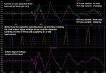
Like you, many people seem to have a "voltage-centric" point of view of power supplies and power distribution within a circuit or system. I did that, too. But I later found that it is not a very helpful mental model.

Take, for example, an audio power amplifier and its power supply. Everyone seems to worry mostly about the ripple voltage of the supply. But, first of all, what does the supply do? What is it for? What does it need to be good at doing? First, think about the high-power output transistors in the amplifier. They are controllable resistances, controlled by the small-signal stages. They are controllable current valves! The music signal that makes the sound come from the speakers is, exactly, the current from the power supply. The supply's primary purpose is to be able to supply the needed current, with high fidelity. Keeping the voltage of the supply constant and ripple-free is secondary. Most amplifier circuits have a good power supply rejection ratio, anyway. The current is where the action is!

And speaking of the ripple voltage, forget about the textbook plots of sawtooth-like ripple. Since the current supplied by the power supply reservoir caps and the decoupling caps will be shaped exactly like the music signal, the voltage across the caps, i.e. the power supply rail voltage, will be shaped by the integral of the music signal (i = C dv/dt so integrate to get v = (1/C)∫i(t) dt). The only time you would see the textbook-type sawtooth-like ripple would be when the amplifier output was constant DC.

See the attached image from an LT-Spice simulation of an audio power amplifier and power supply (right-click on thumbnail at top of post and select "open link in new window"). One of the nice things about LT-Spice is that it can use WAV files as inputs and outputs. That image shows the response for part of a WAV file of the intro of "Highway to Hell", a song by AC/DC. As you can plainly see, the capacitors are there to accurately provide the current to produce the music. However, they do need to be large-enough so that the rail voltage doesn't dip too far, such that clipping would occur. And they do absorb the 120 Hz or 100 Hz current pulses from the rectifiers, essentially filtering out much of the 120 or 100 Hz.

So the current from the supply caps IS the signal (most of the time). When more current is supplied, the rail voltage (cap voltage) drops as a result. The capacitors are not reacting to, or filtering, changes of the rail voltage. They are CAUSING the changes in the rail voltage, by supplying the current that is the signal. A larger capacitance will cause a smaller voltage dip, while still supplying the same current in the same time interval.

Decoupling capacitors are meant to decouple one part of a circuit from the rest, in terms of not disturbing the rest of the circuit's rail voltage. They act as a local supply of current, so that the main power supply doesn't have to, and thus the rail disturbances (and ground bounce) for the rest of the circuit are minimized, and there is less potential for coupling between different parts of a circuit that use the same supply. (That's more true at high frequencies.) Note, too, that the large and/or dynamic currents can then be kept localized, flowing in much smaller loops, which provides a much lower potential for radiated electromagnetic fields that could couple with other parts of a circuit, or interfere with other devices.

The other reason to use decoupling capacitance right at an active load point is for high frequencies, when the high slew rates of the needed currents would cause voltages to be induced across the parasitic inductance (and resistance) of the power and ground rail conductors, themselves. So, again, their purpose is to be a local supply of current. You can also think of them in terms of PSU impedance. The "power supply output impedance" is useless, if the supply output is inches away and you are dealing with high-frequency current demands. The only place the supply impedance matters is right at the power supply pin of the active device that draws the current! And the parasitic inductance and resistance of the power and ground rail conductors, alone, wreck the PSU output impedance. So a decoupling capacitance, right at the power pins, is needed, so that the power pins see a low-enough impedance, so they can draw fast-rising currents.

An audio amplifier is not a great example, for the high frequency case, since most audio frequencies can be pulled from a distant power supply reservoir capacitor without any significant effects due to the rail parasitics. However, even if the amplifier's input is band-limited to only audible frequencies (say 22 kHz), the typical audio amplifier still needs to be able to respond, internally, to at least a few hundred kilohertz. So while the reservoir capacitance might need to be 10000 to 40000 uF per power rail, to handle most of the audio range, and does not need to be excessively close to the output devices, the highest audio frequencies and the necessary internal frequency response will still mandate the use of something on the order of 10 uF per watt of rated maximum RMS output power, very close to each power output device. On the other hand, from the point of view of keeping the large dynamic currents localized in smaller loops, placing large capacitances near each active high-power audio output device is not without merit.

Cheers,

Tom
 
Last edited:

Status
Not open for further replies.

Similar threads

Part and Inventory Search

Welcome to EDABoard.com

Sponsor

Back
Top