PA3040
Advanced Member level 3

Dear All
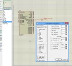
My attached picture for PIC 16f877a seven segment display clock using timer1 external clock
Oscillator mode is enable correctly and my actual hardware is working but Proteus does not working
Please advice, Am I connected correctly watch Crystal to T1OS0 and T1OS1 pins
when I select the internal clock source then it is working properly

Please advice
My attached picture for PIC 16f877a seven segment display clock using timer1 external clock
Oscillator mode is enable correctly and my actual hardware is working but Proteus does not working
Please advice, Am I connected correctly watch Crystal to T1OS0 and T1OS1 pins
when I select the internal clock source then it is working properly
Code:
bsf     T1CON,TMR1CS     ; External clock from pin RC0/T1OSO/T1CKI (on the rising edge)
			bsf		T1CON,T1OSCEN  ;Oscillator is enabled
			bcf		T1CON,T1SYNC  ;Synchronize external clock input
    		bsf     T1CON,TMR1ON     ; turn TMR1 on
    		bsf     T1CON,T1CKPS0    ; set Timer1 Pre-scale to 1:8 using
    		bsf     T1CON,T1CKPS1
Please advice
Last edited: