Continue to Site

Welcome to EDAboard.com

Welcome to our site! EDAboard.com is an international Electronics Discussion Forum focused on EDA software, circuits, schematics, books, theory, papers, asic, pld, 8051, DSP, Network, RF, Analog Design, PCB, Service Manuals... and a whole lot more! To participate you need to register. Registration is free. Click here to register now.

Analogue Active Noise Cancellation Headphones

Status
Not open for further replies.
how to use it?? nd how it looks like??
kindly send me some detail :)
 

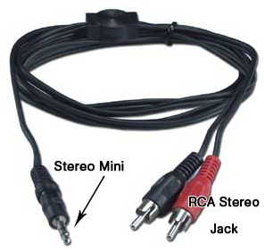
You need to plug a stereo patch cable into your computer. A common type is the 1/8 inch 'mini' size.

Typical cable like you would buy at the store for a few dollars. (Or on Ebay.)

7940152700_1368207525.png


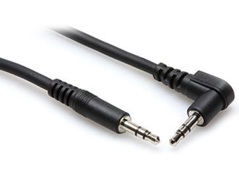
Or identical plug at both ends:

9874733500_1368207833.png


The other end can go to a matching mini jack, installed in your project enclosure. Then connect wires from the jack to your circuit board.

Or if you would rather make a permanent connection, just clip the plug(s) off one end, run the cable into your enclosure, and solder the wires directly to your circuit board.
 
Do you mean how to ensure quality of signal that pass cable ? Or how to correct that error in term of engineering work ?
Ok, All engineer is not designer although profesional designer, but how to is work of engineer, I think ?


Perhap for somebody on this rule !
 
hello !
have a good day !
i am implementing above mentioned Noise cancelling circuit on breadboard .. i get out output after 2nd stage but when i just start to take output after 3rd stage, the output of previous two stages also get badly distorted.. and also OP-AMPs get fused.. i am too worry cause of it
kindly help me
Fleming

- - - Updated - - -

hello !
have a good day !
i am implementing above mentioned Noise cancelling circuit on breadboard .. i get out output after 2nd stage but when i just start to take output after 3rd stage, the output of previous two stages also get badly distorted.. and also OP-AMPs get fused.. i am too worry cause of it
kindly help me
Fleming
 

You should simulate your circuit with commercial model or spice model in your circuit should/must be edited to like to utmost your chip and others.
Read spec in datasheets , to set right mode of operation. Maybe you will get the simple example circuit to applied to your circuit in datasheet.

Try study Example Questions in the Opamp book , because there're numerics calculation.
 
but when i just start to take output after 3rd stage, the output of previous two stages also get badly distorted.. and also OP-AMPs get fused.. i am too worry cause of it
kindly help me
Fleming

One possibility: Op amps do not like for input signals to travel beyond the supply rails. This can cause the device to be ruined.

I am assuming your power supply is not too much.

When the previous stage gets distorted, it suggests either:
* low resistor values somewhere, which draw too much current,
or
* low resistor values allowing a disorted or clipped output signal from your third stage, to get back to the second stage.
 
okay let me do analysis again..
i'll reply back to inform you..
Fleming

- - - Updated - - -

how can i implement this ( active noise cancellation circuit) in micro controller??
i wanna also implement this project using microcontroller..
so kindly help me :)
Fleming

- - - Updated - - -

how can i implement this ( active noise cancellation circuit) in micro controller??
i wanna also implement this project using microcontroller..
so kindly help me :)
Fleming
 

Mixed signal ? Both Analog and Digital parts is in one circuit, Try make first part to be digital circuit rather than Analog circuit .

Try to read how to work with the good design paper or book, Another way is buying the small microcontroller board to testing your programming with microcontroller IC .


NOT HARD TO LEARN , IT LIKE CHESS LEARNNING , I thinks.(In the first concept)
 
no..
what this above mentioned analogue circuit is doing, i wanna same to implement using micro controller
i dont know much about its programming..
so kindly help me
 

OK, I guess your circuit is Analog Filter with one Op-amp and a number of resistor to config sensitivity(In Analog part).

you should to do circuit analysis to find the transfer function then do bold plot analysis to find input voltage maximum, Op amp should operate at voltage supply > input voltage and supply mode of operation that can find in Op amp datasheet.
 
  • Like
Reactions: fadverd

    V

    Points: 2
    Helpful Answer Positive Rating

    fadverd

    Points: 2
    Helpful Answer Positive Rating
OK, I guess your circuit is Analog Filter with one Op-amp and a number of resistor to config sensitivity(In Analog part).

you should to do circuit analysis to find the transfer function then do bold plot analysis to find input voltage maximum, Op amp should operate at voltage supply > input voltage and supply mode of operation that can find in Op amp datasheet.

i wanna implement this circuit in micro controller.. so help me in that regard
 

Hi,
Even I wanted to do the project and previously collected some info about this: Microcontroller based ANC. Hope you find it interesting too. Due to lack of further interest and time, I had to stop. Hope to help you more on this too.
Read and get some idea from the attached file. Source is: **broken link removed**
 

Attachments

  • sloa182.pdf
    1 MB · Views: 221
Do you want to apply Microcontroller to be DSP CHIP ? In the past , Someone had impremented in C/C++ language but he use Microprocessor form System on chip(SOC) + ASIC .

But one don't have permitted , finally .

- - - Updated - - -

Do you want to apply Microcontroller to be DSP CHIP ? In the past , Someone had impremented in C/C++ language but he use Microprocessor form System on chip(SOC) + ASIC .

But one don't have permitted , finally .
 

Well, before any further discussion, why would you like to implement it using MCU? I lost my interest in the project coz it actually is much better in its analog form, also its digital version will need more processing power.
 
why would you like to implement it using MCU? I lost my interest in the project cause it actually is much better in its analog form, also its digital version will need more processing power
actually in analogue domain i have to use 6 op amps and many other components.. thus its too complicated to work with it and too get final output.. i have got output after first 2 stages but that's not actually a stable output.. and i am still unable to get output after 3rd and final stage.. and also the outputs which i have got are with input of Sinusoidal wave.. so it'll be more complex to work with audio signal instead of sinusoidal wave.. so that's why i am thinking to implement it using MCU.. I have gone throw this report which you sent me, but its too complicated and tough to understand too..

- - - Updated - - -

Well, before any further discussion, why would you like to implement it using MCU? I lost my interest in the project coz it actually is much better in its analog form, also its digital version will need more processing power.

actually in analogue domain i have to use 6 op amps and many other components.. thus its too complicated to work with it and too get final output.. i have got output after first 2 stages but that's not actually a stable output.. and i am still unable to get output after 3rd and final stage.. and also the outputs which i have got are with input of Sinusoidal wave.. so it'll be more complex to work with audio signal instead of sinusoidal wave.. so that's why i am thinking to implement it using MCU.. I have gone throw this report which you sent me, but its too complicated and tough to understand too..

- - - Updated - - -

Do you want to apply Microcontroller to be DSP CHIP ? In the past , Someone had impremented in C/C++ language but he use Microprocessor form System on chip(SOC) + ASIC .

But one don't have permitted , finally .

- - - Updated - - -

Do you want to apply Microcontroller to be DSP CHIP ? In the past , Someone had implemented in C/C++ language but he use Microprocessor form System on chip(SOC) + ASIC .

But one don't have permitted , finally .
nope
i am just talking about MCU.. just to write some code like using PIC micro controller and to attach this circuitry with headphones..
in short i want that a single MCU do what these 6 op apms do which i am trying to implement
 

in short i want that a single MCU do what these 6 op apms do which i am trying to implement
You can only give the digital control signals using a MCU. The full circuit implemented using a MCU only? I dont think thats possible.
 
You can only give the digital control signals using a MCU. The full circuit implemented using a MCU only? I dont think thats possible.

i think its possible.. if i gave an audio siganl to ADC, the resulting output( digitized signal) is then to be inverted and this inverted signal then is to add with actual siganl, then their output (cancelled output) is to sent to DAC and then finally its output is to sent to headphones...
isn't possible??

- - - Updated - - -

You can only give the digital control signals using a MCU. The full circuit implemented using a MCU only? I dont think thats possible.

i think its possible.. if i gave an audio siganl to ADC, the resulting output( digitized signal) is then to be inverted and this inverted signal then is to add with actual siganl, then their output (cancelled output) is to sent to DAC and then finally its output is to sent to headphones...
isn't possible??
 

What you are basically doing is using the MCU to get the control signals for your circuit. This means you can reduce the amount of your hardware circuitry but can not actually eliminate all of it. Now if you want to write a long program for this. As for eg: inverting the signal.
 

Fully digital is special case, hard to imprement in MCU. But FPGA may be solution of this case , rather.
 

Status
Not open for further replies.

Part and Inventory Search

Welcome to EDABoard.com

Sponsor

Back
Top