Continue to Site

Welcome to EDAboard.com

Welcome to our site! EDAboard.com is an international Electronics Discussion Forum focused on EDA software, circuits, schematics, books, theory, papers, asic, pld, 8051, DSP, Network, RF, Analog Design, PCB, Service Manuals... and a whole lot more! To participate you need to register. Registration is free. Click here to register now.

[SOLVED] LEDS do not turn ON, with my ADC code please Assist..

Status
Not open for further replies.

Yamber

Newbie level 5
Newbie level 5
Joined
May 6, 2013
Messages
8
Helped
0
Reputation
0
Reaction score
0
Trophy points
1,281
Activity points
1,330
Hello Guys,
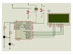
I'm using LCD 20 x 4 LCD, PIC18f2620 as ou can see on the picture. Here is my code. Please assist to find out why the LEDs are not coming on.
Thanks.
ADC.jpg

Code:
#include "Xa.h"
#include <stdio.h>
#include <stdlib.h>
#include <delays.h>

#define LED_RED LATCbits.LATC0
#define LED_GREEN LATCbits.LATC1

void init_IO(void);
void init_XLCD(void);
void DelayXLCD(void);
void DelayPORXLCD(void);
void DelayFor18TCY(void);
void init_ADC (void);

unsigned int ADCResult [2];
float voltage;
unsigned char ResultStr [10];

int main(void) {
 //   long status;
    unsigned char i;
    init_ADC ();
    init_XLCD ();
//************************************
    putrsXLCD(" SYSTEM READY");
    __delay_ms(80);
    WriteCmdXLCD (0x01);
    //********************************
    while (1){
        for ( i = 0; i < 2; i++){
            ADCON0bits.CHS = i;
            DelayFor18TCY();
            ConvertADC ();
            while (BusyXLCD ());
            ADCResult [i] = (unsigned int) ReadADC ();}
           
//***********************************
        for ( i = 0;i < 2; i++){
             voltage = (ADCResult [1]* 5.0/1024);
            sprintf (ResultStr, "AD%1u = %4u ",i , ADCResult [i]);
            if (i ==1)
            SetDDRamAddr (0x40);
            putrsXLCD (ResultStr);
            SetDDRamAddr (0x13);
            sprintf (ResultStr," Voltage = %f ", voltage);
            putrsXLCD (ResultStr);
//            putrsXLCD (  );
            SetDDRamAddr (0x54);
            putrsXLCD("THIS IS NOT GOOD");
           
          //  putrsXLCD (ResultStr);
        }
        WriteCmdXLCD (0x02);//Home Screen

     
    if (voltage > 0)
        LED_RED = 1;
        LED_GREEN = 0;
    __delay_ms(60);
        LED_GREEN = 1;
    __delay_ms(60);

  }
 }


void init_XLCD(void) {
    OpenXLCD(FOUR_BIT & LINES_5X7);
    while (BusyXLCD());
    WriteCmdXLCD(0x06);//move cursor don't shift display
    WriteCmdXLCD(0x0C);// Turn display without cursor
    WriteCmdXLCD(0x01);//Clear Screen
}

void init_ADC (void){
    OpenADC (ADC_FOSC_2 & ADC_RIGHT_JUST & ADC_2_TAD,
             ADC_CH0 & ADC_INT_OFF & ADC_REF_VDD_VSS,
             ADC_2ANA);
}
void DelayXLCD(void){
Delay1KTCYx(20);
   // __delay_ms(20);
}

void DelayPORXLCD(void){
    Delay1KTCYx (60);

}

void DelayFor18TCY(void){
    Delay10TCYx (20);
    return;
}
void init_IO (void){
    OSCCON = 0x76;
    PORTC  =0x00;
 //   PORTC = 0xFF;
    TRISC = 0;
   
}
 

@Yamber,

You have an init_IO function but you're not calling it on your main function, usualy on the IO init function you have to configure all your MCU registers regarded to the port/pins as pin direction, current drive, etc.

Another think that may be wrong is the way your're polarizing the LEDs, on such configuration they takes all the current from the mcu pin, and regularly mcu pins doesn't drive enough current for LEDs, try flipping the LED terminals and instead to attach the LED cathode to the ground attach the anode to VCC, this way you drive current to the pin instead.

Hope this helps,
 
  • Like
Reactions: Yamber

    Yamber

    Points: 2
    Helpful Answer Positive Rating
ADC solved.jpg
- - - Updated - - -

@Snicolasss,
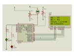
Tnx man, I get what u are saying, problem solved.
Regards.:smile:

Code:
int main(void) {
    init_IO ();
    PORTC = 0x00;
 //   long status;
    unsigned char i;
    init_ADC ();
    init_XLCD ();
 
Last edited:

Regarding PIC drivers Absolute max is 20 mA for either state

however the internal power dissipation is lower with the Low state due to lower ESR in the driver.

from page 337 in the spec.

Output Low Voltage I/O ports — 0.6 V IOL = 8.5 mA, VDD = 4.5V, -40°C to +85°C D083 OSC2/CLKO (RC, RCIO, EC, ECIO modes)
VOL = 0.6 V max @IOL = 1.6 mA, VDD = 4.5V,

Output High Voltage I/O ports
VOH = VDD – 0.7 max @IOH = -3.0 mA, VDD = 4.5V

ESR =internal drop voltage/current
thus VOH = 0.7V/3mA = 233 Ohm thus short circuit to ground = 4.5V/233=16 mA
and VOL = 0.6V/1.6mA= 375 Ohm thus short cct to Vcc = 4.5/375=12 mA

These are using max voltage meaning worst case ESR, best case is unspecified

Using 150R external resistor IOHmax with a 3.5V green implies a 2V drop on Rext + ESR (ESR = R internal =233 for VOH) Rtotal = 150+233=383

IOH = 2V/383 =5.2mA this is safe for the PIC
 
  • Like
Reactions: Yamber

    Yamber

    Points: 2
    Helpful Answer Positive Rating
Status
Not open for further replies.

Similar threads

Part and Inventory Search

Welcome to EDABoard.com

Sponsor

Back
Top