Continue to Site

Welcome to EDAboard.com

Welcome to our site! EDAboard.com is an international Electronics Discussion Forum focused on EDA software, circuits, schematics, books, theory, papers, asic, pld, 8051, DSP, Network, RF, Analog Design, PCB, Service Manuals... and a whole lot more! To participate you need to register. Registration is free. Click here to register now.

4 bit LCD Code needed

Status
Not open for further replies.
Advanced Member level 6
Joined
Dec 4, 2012
Messages
4,280
Helped
822
Reputation
1,654
Reaction score
791
Trophy points
1,393
Location
Bangalore, India
Activity points
0
I need 4 bit LCD Code. I know that first the Upper nibble of data or command is sent and then Lower nibble of data or command is sent. I have code but I have to define data port like

#define LCD_DATAPORT PORTD

and then send upper nibble and lower nibbles to LCD_DATAPORT and after assigning each nibble I have to toggle EN pin. What I want is...

I will be using pins like

LCD_D4 = PORTBbits.RB0
LCD_D5 = PORTCbits.RC7
LCD_D6 = PORTDbits.RD1
LCD_D7 = PORTAbits.RA0

i.e., I must be able to use any pins for lcd data

So, I need code which assigns bits of the upper and lower nibbles to individual pins and then toggles the EN pin.
 
Last edited:

Justin you didn't understand my question.

I know that I can use something like this if I use #define LCD_DATA PORTD

LCD_DATA=(val&0x0f);
LCD_STROBE;
LCD_DATA =((val>>4)&0x0f);
LCD_STROBE;

I don't want to use LCD_DATA instead I want to send (value&0x0f) in bits to individual pins.

If my LCD D4 to D7 pins are connected to RA0, RB2, RC4, RD7 and value is 0xFE then (value&0x0f) = 0x0E

0x0E = 0b00001110

I have to send 0b00001110 to LCD D4-D7 pins.

RA0 should be 1
RB2 should be 1
RC4 should be 1
RD7 should be 0

Is this right?

LCD_D4 = (val&0x0f) >> 3;
LCD_D5 = (((val&0x0f) >> 2) & 0b00000001);
LCD_D6 = ((val&0x0f) >> 1) & 0b00000001;
LCD_D7 = (val&0x0f) & 0b00000001;
LCD_STROBE
LCD_D4 = ((val>>4)&0x0f) >> 3;
LCD_D5 = (((val>>4)&0x0f) >> 2) & 0b00000001);
LCD_D6 = (((val>>4)&0x0f) & 0b00000001;
LCD_D7 = ((val>>4)&0x0f) & 0b00000001;
LCD_STROBE

Your code is not working...

Code C - [expand]
1
2
3
4
5
6
7
8
9
10
11
12
13
14
15
16
17
18
19
20
21
22
23
24
25
26
27
28
29
30
31
32
33
34
35
36
37
38
39
40
41
42
43
44
45
46
47
48
49
50
51
52
53
54
55
56
57
58
59
60
61
62
63
64
65
66
67
68
69
70
71
72
73
74
75
76
77
78
79
80
81
82
83
84
85
86
87
88
89
90
91
92
93
94
95
96
97
98
99
100
101
102
103
104
105
106
107
108
109
110
111
#include <htc.h>
#define _XTAL_FREQ 4000000 // 4 MHz clock 
 
__CONFIG(0X3F39);
#define LCD_EN RC6
#define LCD_RS RC7
#define LCD_DATA    PORTD
#define LCD_STROBE  LCD_EN = 1; __delay_ms(1); LCD_EN=0;
 
void lcddata(unsigned char value);
void lcdcmd(unsigned char value);
void lcd_init();
void display ();
 
unsigned char time [6] = {"Time:"}, val;
 
void lcd_init() 
{
       LCD_EN=0;
       LCD_RS = 0; 
       __delay_us(10);  
    LCD_DATA=0X0c;
         LCD_EN = 1;
        __delay_ms(2);
 
       LCD_RS = 0; 
       __delay_us(10);  
    LCD_DATA=0X0c;
        LCD_STROBE;
    __delay_ms(2);
 
         LCD_RS = 0; 
       __delay_us(10);  
    LCD_DATA=0X0c;
        LCD_STROBE;
    __delay_ms(2);
 
        LCD_RS = 0; 
       __delay_us(10);  
    LCD_DATA=0X04;
        LCD_STROBE;
    __delay_ms(2);
 
    lcdcmd(0X28);
    __delay_ms(5);
    lcdcmd(0X0);
    __delay_ms(5);
    lcdcmd(0X01);
    __delay_ms(5);
    lcdcmd(0X06);
    __delay_ms(5);
 
}
 
void display (){
    lcdcmd(0x80);
        for (char i=0;i<5;i++){
            lcddata(time[i]);
            
                    }
        }


void lcddata(unsigned char val)
    {
//8bit reversing 
 
val = (val & 0x0F) << 4 | (val & 0xF0) >> 4;
val = (val & 0x33) << 2 | (val & 0xCC) >> 2;
val = (val & 0x55) << 1 | (val & 0xAA) >> 1;
 
 
LCD_RS = 1; 
LCD_DATA=(val&0x0f);
LCD_STROBE;
LCD_DATA =((val>>4)&0x0f);
LCD_STROBE;
__delay_ms(10);
    }
 
 
void lcdcmd(unsigned char val)
    {
 
//8bit reversing 
val = (val & 0x0F) << 4 | (val & 0xF0) >> 4;
val = (val & 0x33) << 2 | (val & 0xCC) >> 2;
val = (val & 0x55) << 1 | (val & 0xAA) >> 1;
 
LCD_RS = 0; 
LCD_DATA=(val&0x0f);
LCD_STROBE;
LCD_DATA =((val>>4)&0x0f);
LCD_STROBE;
__delay_ms(10);
    }
void main(){
    TRISC = 0x00;
    TRISD = 0x00;
    PORTC = 0x00;
    PORTD = 0x00;
            
        lcd_init();
        display();       
            while(1){   
                ;
        
            }
}


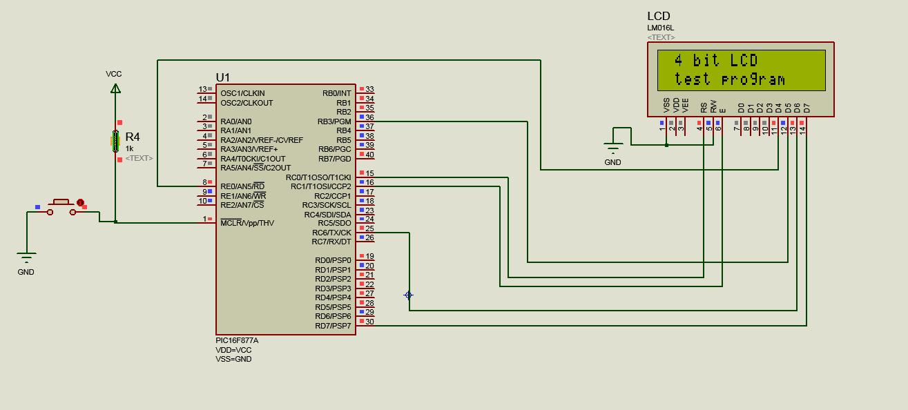
See this simulation. I have done it for 8 bit LCD. Any pin can be used for lcd data port.
90634d1367820294-8bitlcd2.jpg
 

Attachments

  • lcd4bitjustin.rar
    80.7 KB · Views: 183
  • lcd8bit2.rar
    13.1 KB · Views: 146
  • 8bitlcd2.jpg
    8bitlcd2.jpg
    264.8 KB · Views: 283
Last edited:

Your compiler *may* let you declare a structure containing the individual pin names, I use a different one so I'm not sure.

Otherwise, the way to do it is to "#define" the pin names at the top of the program so you can use names in the code (an easily change them if necessary) then use the method you show already. Remember that the LCD only accepts data when LCD_STROBE is called so you can freely set the pins at any time before then. Please check, because each compiler produces it's own code but you might find it quicker to use something like this to decide whether the pin should be set or not:
Code:
#define LCD_D4 PORTBbits.RB0
#define LCD_D5 PORTCbits.RC7
#define LCD_D6 PORTDbits.RD1
#define LCD_D7 PORTAbits.RA0

// then to set/reset individual bits use

LCD_D4 = (value & 0x01 == 0)?0:1;
LCD_D5 = (value & 0x02 == 0)?0:1;
LCD_D6 = (value & 0x04 == 0)?0:1;
LCD_D7 = (value & 0x08 == 0)?0:1;

If that looks promising, you could see if changing the lines like this is better: LCD_D4 = (value & 0x01)?1:0;
I can't simulate it for you at the moment but it's worth tryng.

Brian.
 
Your code is not working Justin_Cubetech

I have a working 4-bit LCD Code.

The code needs LCD data port to be defined like

#define LCD_PORT PORTD

code uses these instructions.


Code C - [expand]
1
2
3
4
5
6
7
8
9
10
11
12
13
14
15
16
17
18
19
20
21
LCD_PORT &= 0x0F;// Make Data pins zero
    
LCD_PORT |= (Command&0xF0);  // Write Upper nibble of data
 
LCD_EN = 1;  // Give a pulse on E pin
    
__delay_us(EN_Delay);      // so that LCD can latch the
    
LCD_EN = 0;                
__delay_us(EN_Delay);
 
LCD_PORT &= 0x0F;// Make Data pins zero
    
LCD_PORT |= ((Command<<4)&0xF0); // Write Lower nibble of data
 
LCD_EN = 1;  // Give a pulse on E pin
    
__delay_us(EN_Delay);      // so that LCD can latch the
    
LCD_EN = 0;                
__delay_us(EN_Delay);


I want to modify the 4 statements which assign value to LCD_PORT such that any pin can be used for LCD data. Please tell me how to set value of upper nibble and lower nibble to individual pins.

I code should allow to use any pins for LCD data and if PORTB is used for LCD data then PORTB3 to PORTB7 will be used for data but the values of PORTB0 to PORTB3 should not get affected as it may be connected to other devices.

I also need code which assigns upper and lower nibbles to individual pins so that I can use any pins for 4-bit LCD data like RA0, RB7, AC6, RD1
 

Attachments

  • 8bitlcdjustinv3.rar
    30 KB · Views: 163
Last edited:

betwixt suggested method is working.


Code:
#define ENBL EN=1; __delay_ms(1);EN=0; 	

#define RS RC0
#define EN RC1

#define LCD_D4 RE0
#define LCD_D5 RB3
#define LCD_D6 RC6
#define LCD_D7 RD7
	
void lcd_send(char type,unsigned char val)	  //type 0=command 1=data  lcd value  	 
{
 RS=type;
     
    
LCD_D4 = (val & 0x10)?1:0;
LCD_D5 = (val & 0x20)?1:0;
LCD_D6 = (val & 0x40)?1:0;
LCD_D7 = (val & 0x80)?1:0;
     

     ENBL; 
     
LCD_D4 = (val & 0x01)?1:0;
LCD_D5 = (val & 0x02)?1:0;
LCD_D6 = (val & 0x04)?1:0;
LCD_D7 = (val & 0x08)?1:0;     
     
ENBL;
__delay_us(100);
}


6197160900_1367849220.png
 
Last edited:
Justin and you post the full code?

What does this piece of code do?


Code C - [expand]
1
2
3
4
LCD_D4 = (val & 0x10)?1:0;
LCD_D5 = (val & 0x20)?1:0;
LCD_D6 = (val & 0x40)?1:0;
LCD_D7 = (val & 0x80)?1:0;


A problem throughout this thread is that it's cheerfully mixing example codes for different processors and compilers without showing the exact IO library definitions. We experienced a similar problem in another recent thread. https://www.edaboard.com/threads/287703/

Of course, the LCD handling as such can be easily ported between processors. But you have to check that the code is actually operating I/O pins instead of toggling non-existing memory locations where another processor might have it's I/O registers...

In the present case, you have to check that PORTBbits.RB0 actually accesses the respective output bit. I presume it does, but you can't be sure.
 
Hey jayanth, I'm not sure you've been able to use the code justin provided you. Just in case you didn't, I have just released my new HD44780 C Driver (v3.0) which is tested and working, and it's using independent pins to control the LCD, not PORT access for LCD data. Check it out, it's in my signature :)

Anyway, the piece of code you were asking only evaluates if the selected bit is 1 or 0 and assigns the value to the LCD_Dx pins.
 
The example I gave should work on any processor as long as the #define associates the LCD data pin with a real peripheral pin. The other LCD functions are of course specific to the compiler itself.

The "LCD_D4 = (val & 0x10)?1:0;" construct tests the expression in the brackets and returns the first value '1' if it is true and the second value '0' if it is false. So it sees if "val & 0x10" equates to zero or not and assigns the value 1 or 0 to the pin defined as LCD_D4. It's called the 'ternary' operator.

Brian.
 
Thanks FvM, Justin, betwixt, and T3STY.

@betwixt

I understood about ternary operator. I have another question. What is the logic of using 0x10, 0x20, 0x40, and 0x80 for the test? Does it test for a particular bit of a byte? If yes, Which bits? What If I want to use the same logic for 8-bit LCD. what values should I use other than the above 4 to test for each bit of a byte.

Edit:

Ok. In the below piece of code it tests if bits 4, 5, 6, 7 and 0, 1, 2, 3 are true or false and returns 1 if true and 0 if false.


Code C - [expand]
1
2
3
4
5
6
7
8
9
10
11
12
LCD_D4 = (val & 0x10)?1:0;
LCD_D5 = (val & 0x20)?1:0;
LCD_D6 = (val & 0x40)?1:0;
LCD_D7 = (val & 0x80)?1:0;
     
 
     ENBL; 
     
LCD_D4 = (val & 0x01)?1:0;
LCD_D5 = (val & 0x02)?1:0;
LCD_D6 = (val & 0x04)?1:0;
LCD_D7 = (val & 0x08)?1:0;


I did the coding for LCD_Cmd() and LCD_Out() functions. I have problem with this LCD_Init() function. betwixt how to change the lines that are commented with //// to use individual port pins for LCD data as shown above?


Code C - [expand]
1
2
3
4
5
6
7
8
9
10
11
12
13
14
15
16
17
18
19
20
21
22
23
24
25
26
27
28
29
30
31
32
33
34
35
36
37
38
39
40
41
42
43
44
45
46
47
48
49
50
51
52
53
54
55
56
57
58
59
60
61
62
63
64
65
66
67
68
69
70
void LCD_Init()
{
 
  ///////////////// Reset process from datasheet //////////////
   _delay_ms(30);
 
    ////LCD_PORT &= 0x0F;             // Make Data pins zero
    LCD_D4 = (val & 0x10)?1:0;
    LCD_D5 = (val & 0x20)?1:0;
    LCD_D6 = (val & 0x40)?1:0;
    LCD_D7 = (val & 0x80)?1:0;
    
    ////LCD_PORT |= 0x30;             // Write 0x3 value on data bus
 
    LCD_EN = 1;                // Give a pulse on E pin
    _delay_ms(EN_Delay);      // so that LCD can latch the
    LCD_EN = 0;                // data from data bus
    _delay_ms(EN_Delay);
 
    _delay_ms(6);
 
    LCD_PORT &= 0x0F;             // Make Data pins zero
    LCD_D4 = (val & 0x10)?1:0;
    LCD_D5 = (val & 0x20)?1:0;
    LCD_D6 = (val & 0x40)?1:0;
    LCD_D7 = (val & 0x80)?1:0;
 
    ////LCD_PORT |= 0x30;             // Write 0x3 value on data bus
 
    LCD_EN = 1;                // Give a pulse on E pin
    _delay_ms(EN_Delay);      // so that LCD can latch the
    LCD_EN = 0;                // data from data bus
    _delay_ms(EN_Delay);
 
    _delay_ms(3);
 
    LCD_PORT &= 0x0F;             // Make Data pins zero
    LCD_D4 = (val & 0x10)?1:0;
    LCD_D5 = (val & 0x20)?1:0;
    LCD_D6 = (val & 0x40)?1:0;
    LCD_D7 = (val & 0x80)?1:0;
 
    ////LCD_PORT |= 0x30;             // Write 0x3 value on data bus
 
    LCD_EN = 1;                // Give a pulse on E pin
    _delay_ms(EN_Delay);      // so that LCD can latch the
    LCD_EN = 0;                // data from data bus
    _delay_ms(EN_Delay);
 
    _delay_ms(2);
 
    LCD_PORT &= 0x0F;             // Make Data pins zero
    LCD_D4 = (val & 0x10)?1:0;
    LCD_D5 = (val & 0x20)?1:0;
    LCD_D6 = (val & 0x40)?1:0;
    LCD_D7 = (val & 0x80)?1:0;
 
    ////LCD_PORT |= 0x20;             // Write 0x2 value on data bus
 
    LCD_EN = 1;                // Give a pulse on E pin
    _delay_ms(EN_Delay);      // so that LCD can latch the
    LCD_EN = 0;                // data from data bus
    _delay_ms(EN_Delay);
 
    _delay_ms(2);
  /////////////// Reset Process End ////////////////
    LCD_Cmd(0x28);    //function set
    LCD_Cmd(0x0C);    //display on,cursor off,blink off
    LCD_Cmd(0x06);    //entry mode, set increment
}

 
Last edited:

lcd init function


Code:
void lcd_init()  
{   

       EN=0;
       RS=0;
       __delay_us(10); 
       
LCD_D4 = 1;
LCD_D5 = 1;
LCD_D6 = 0;
LCD_D7 = 0;  
      
//	LCD=0X30;
	
     	ENBL;
       	__delay_ms(2);

       RS=0;
       __delay_us(10);  
       
LCD_D4 = 1;
LCD_D5 = 1;
LCD_D6 = 0;
LCD_D7 = 0;          
       
//	LCD=0X30;
     	ENBL;
	__delay_ms(2);

        RS=0;
       __delay_us(10);  
//	LCD=0X0c;

LCD_D4 = 1;
LCD_D5 = 1;
LCD_D6 = 0;
LCD_D7 = 0;   

//	LCD=0X30;

       	ENBL;
	__delay_ms(2);

       RS=0;
       __delay_us(10);  
       
LCD_D4 = 0;
LCD_D5 = 1;
LCD_D6 = 0;
LCD_D7 = 0;         
       
       
//	LCD=0X20;

     	ENBL;
	__delay_ms(2);

	lcd_send(0,0X28);
	__delay_ms(5);
	lcd_send(0,0X0C);
	__delay_ms(5);
	lcd_send(0,0X01);
	__delay_ms(5);
	lcd_send(0,0X06);
	__delay_ms(5);

}
 
I have done that already Justin. Thanks.

Why this code is not working. I am attaching MPLAB Hi-Tech C project files and Proteus file. Clock is 20 MHz, Config Bits set in IDE. Extract the files to folder on Desktop.

This is my Code.


Code C - [expand]
1
2
3
4
5
6
7
8
9
10
11
12
13
14
15
16
17
18
19
20
21
22
23
24
25
26
27
28
29
30
31
32
33
34
35
36
37
38
39
40
41
42
43
44
45
46
47
48
49
50
51
52
53
54
55
56
57
58
59
60
61
62
63
64
65
66
67
68
69
70
71
72
73
74
75
76
77
78
79
80
81
82
83
84
85
86
87
88
89
90
91
92
93
94
95
96
97
98
99
100
101
102
103
104
105
106
107
108
109
110
111
112
113
114
115
116
117
118
119
120
121
122
123
124
125
126
127
128
129
130
131
132
133
134
135
136
137
138
139
140
141
142
143
144
145
146
147
148
149
150
151
152
153
154
155
156
157
158
159
160
161
162
163
164
165
166
167
168
169
170
171
172
173
174
175
176
177
178
179
180
181
182
183
184
185
186
187
188
189
190
191
192
193
194
195
196
197
198
199
200
201
202
203
204
205
206
207
208
209
210
211
212
213
214
215
216
217
218
219
220
221
222
223
224
225
226
227
228
229
230
231
232
233
234
235
236
237
238
239
240
241
242
243
244
245
246
247
248
249
250
251
252
253
254
255
256
257
258
259
260
261
262
263
264
265
266
267
268
269
/*
 * main.c
 *
 * Created: 5/7/2013 9:09:11 AM
 * Author: Jayanth Devarayanadurga
 */ 
 
#include <htc.h>
 
//Define CPU Frequency
//This must be defined, if __delay_ms() or
//__delay_us() functions are used in the code
#define _XTAL_FREQ   20000000
 
// Configuration word for PIC16F877
//__CONFIG( FOSC_HS & WDTE_OFF & PWRTE_ON & CP_OFF & BOREN_ON
//  & LVP_OFF & CPD_OFF & DEBUG_OFF);
    
#define LCD_RS PORTBbits.RB0
#define LCD_EN PORTBbits.RB7
#define LCD_D4 PORTCbits.RC0
#define LCD_D5 PORTCbits.RC4
#define LCD_D6 PORTDbits.RD3
#define LCD_D7 PORTDbits.RD6
 
#define LCD_RS_Direction TRISBbits.TRISB0
#define LCD_EN_Direction TRISBbits.TRISB7
#define LCD_D4_Direction TRISCbits.TRISC0
#define LCD_D5_Direction TRISCbits.TRISC4
#define LCD_D6_Direction TRISDbits.TRISD3
#define LCD_D7_Direction TRISDbits.TRISD6
 
 
#define _LCD_FIRST_ROW          0x80     //Move cursor to the 1st row
#define _LCD_SECOND_ROW         0xC0     //Move cursor to the 2nd row
#define _LCD_THIRD_ROW          0x94     //Move cursor to the 3rd row
#define _LCD_FOURTH_ROW         0xD4     //Move cursor to the 4th row
#define _LCD_CLEAR              0x01     //Clear display
#define _LCD_RETURN_HOME        0x02     //Return cursor to home position, returns a shifted display to
                                         //its original position. Display data RAM is unaffected.
#define _LCD_CURSOR_OFF         0x0C     //Turn off cursor
#define _LCD_UNDERLINE_ON       0x0E     //Underline cursor on
#define _LCD_BLINK_CURSOR_ON    0x0F     //Blink cursor on
#define _LCD_MOVE_CURSOR_LEFT   0x10     //Move cursor left without changing display data RAM
#define _LCD_MOVE_CURSOR_RIGHT  0x14     //Move cursor right without changing display data RAM
#define _LCD_TURN_ON            0x0C     //Turn Lcd display on
#define _LCD_TURN_OFF           0x08     //Turn Lcd display off
#define _LCD_SHIFT_LEFT         0x18     //Shift display left without changing display data RAM
#define _LCD_SHIFT_RIGHT        0x1E     //Shift display right without changing display data RAM
 
// Constants
#define EN_Delay 5
 
// Give a pulse on E pin
// so that LCD can latch the
// data from data bus
 
#define LCD_STROBE LCD_EN = 1; __delay_ms(EN_Delay); LCD_EN = 0; __delay_ms(EN_Delay);
 
 
//Function Prototypes
void LCD_Cmd(unsigned char Command);
void LCD_Ch(unsigned int row, unsigned int col, char LCDChar);
void LCD_Init();
void LCD_Out(unsigned int row, unsigned int col, const char *str);
 
void LCD_Cmd(unsigned char Command)
{
    LCD_RS = 0;           // It is a command
 
    LCD_D4 = (Command & 0x10)?1:0;
    LCD_D5 = (Command & 0x20)?1:0;
    LCD_D6 = (Command & 0x40)?1:0;
    LCD_D7 = (Command & 0x80)?1:0;
    LCD_EN = 1;
    __delay_ms(EN_Delay);
    LCD_EN = 0;
    __delay_ms(EN_Delay);
    LCD_D4 = (Command & 0x01)?1:0;
    LCD_D5 = (Command & 0x02)?1:0;
    LCD_D6 = (Command & 0x04)?1:0;
    LCD_D7 = (Command & 0x08)?1:0;
    LCD_EN = 1;
    __delay_ms(EN_Delay);
    LCD_EN = 0;
    __delay_ms(EN_Delay);
 
    if(Command == 0x01)
    __delay_ms(2);              // Delay for cursor to return at zero position
}
 
 
void LCD_Ch(unsigned int row, unsigned int col, char LCDChar)
{
    switch(row){
 
        case 1:
        LCD_Cmd(0x80 + col-1);
        break;
        case 2:
        LCD_Cmd(0xC0 + col-1);
        break;
        case 3:
        LCD_Cmd(0x94 + col-1);
        break;
        case 4:
        LCD_Cmd(0xD4 + col-1);
        break;
    }
 
    LCD_RS = 1;               // It is data
 
    LCD_D4 = (LCDChar & 0x10)?1:0;
    LCD_D5 = (LCDChar & 0x20)?1:0;
    LCD_D6 = (LCDChar & 0x40)?1:0;
    LCD_D7 = (LCDChar & 0x80)?1:0;
    LCD_EN = 1;
    __delay_ms(EN_Delay);
    LCD_EN = 0;
    __delay_ms(EN_Delay);
 
    LCD_D4 = (LCDChar & 0x01)?1:0;
    LCD_D5 = (LCDChar & 0x02)?1:0;
    LCD_D6 = (LCDChar & 0x04)?1:0;
    LCD_D7 = (LCDChar & 0x08)?1:0;
    LCD_EN = 1;
    __delay_ms(EN_Delay);
    LCD_EN = 0;
    __delay_ms(EN_Delay);
}
 
 
void LCD_Init()
{
    LCD_RS = 0;
    LCD_EN = 0;
    LCD_D4 = 0;
    LCD_D5 = 0;
    LCD_D6 = 0;
    LCD_D7 = 0;
    LCD_RS_Direction = 0;
    LCD_EN_Direction = 0;
    LCD_D4_Direction = 0;
    LCD_D5_Direction = 0;
    LCD_D6_Direction = 0;
    LCD_D7_Direction = 0;   
    
    LCD_RS = 0;
        
    ///////////////// Reset process from datasheet //////////////
    __delay_ms(30);
 
    //Make Data pins zero
    
    LCD_D4 = 0;
    LCD_D5 = 0;
    LCD_D6 = 0;
    LCD_D7 = 0;
    
    //Write 0x3 value on data bus
    LCD_D4 = 1;
    LCD_D5 = 1;
    LCD_D6 = 0;
    LCD_D7 = 0;
 
    LCD_EN = 1;
    __delay_ms(EN_Delay);
    LCD_EN = 0;
    __delay_ms(EN_Delay);
 
    __delay_ms(6);
 
    //Make Data pins zero
    
    LCD_D4 = 0;
    LCD_D5 = 0;
    LCD_D6 = 0;
    LCD_D7 = 0;
 
    //Write 0x3 value on data bus
    LCD_D4 = 1;
    LCD_D5 = 1;
    LCD_D6 = 0;
    LCD_D7 = 0;
 
    LCD_EN = 1;
    __delay_ms(EN_Delay);
    LCD_EN = 0;
    __delay_ms(EN_Delay);
 
    __delay_ms(3);
 
    //Make Data pins zero
    
    LCD_D4 = 0;
    LCD_D5 = 0;
    LCD_D6 = 0;
    LCD_D7 = 0;
 
    //Write 0x3 value on data bus
    LCD_D4 = 1;
    LCD_D5 = 1;
    LCD_D6 = 0;
    LCD_D7 = 0;
 
    LCD_EN = 1;
    __delay_ms(EN_Delay);
    LCD_EN = 0;
    __delay_ms(EN_Delay);
 
    __delay_ms(2);
 
    //Make Data pins zero
    
    LCD_D4 = 0;
    LCD_D5 = 0;
    LCD_D6 = 0;
    LCD_D7 = 0;
 
    //Write 0x2 value on data bus
    LCD_D4 = 0;
    LCD_D5 = 1;
    LCD_D6 = 0;
    LCD_D7 = 0;
 
    LCD_EN = 1;
    __delay_ms(EN_Delay);
    LCD_EN = 0;
    __delay_ms(EN_Delay);
 
    __delay_ms(2);
    /////////////// Reset Process End ////////////////
    LCD_Cmd(0x28);    //function set
    LCD_Cmd(0x0C);    //display on,cursor off,blink off
    LCD_Cmd(0x06);    //entry mode, set increment
}
 
void LCD_Out(unsigned int row, unsigned int col, const char *str)
{
    while(*str)
    LCD_Ch(row,col++,*str++);   // print first character on LCD
    row = 1;
    col = 1;
}
 
int main(void){
 
    TRISA = 0x00;
    TRISB = 0x00;
    TRISC = 0x00;
    TRISD = 0x00;
    PORTA = 0x00;
    PORTB = 0x00;
    PORTC = 0x00;
    PORTD = 0x00;
 
    LCD_Init();
    LCD_Cmd(_LCD_CLEAR);
    LCD_Cmd(_LCD_CURSOR_OFF);
 
    LCD_Out(1,1,"PIC18F458");
    LCD_Out(2,1,"LCD 4-bit");
    LCD_Out(3,1,"20X4");
    LCD_Out(4,1,"Working?");
 
    while(1);
 
    return (0);
}


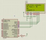
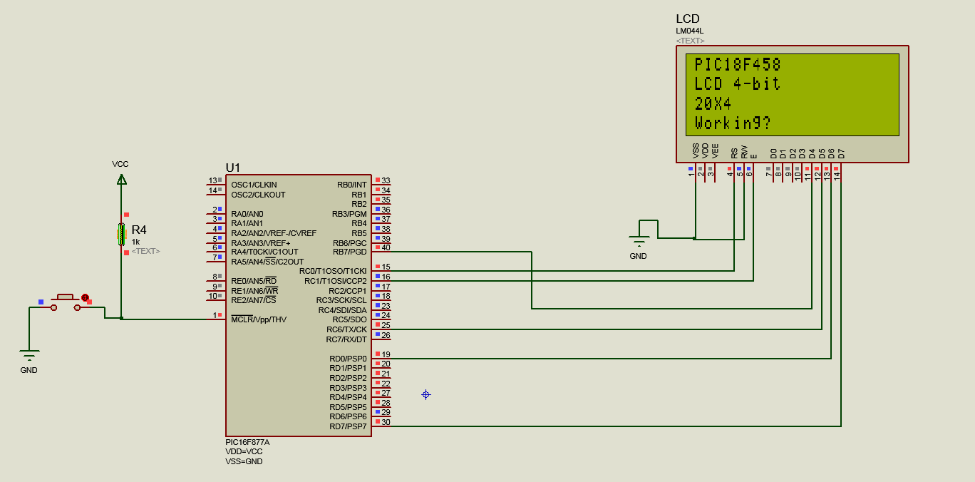
I am attaching another .rar file. It works fine but not the above code. Why?

90684d1367908167-lcd4bit.jpg
 

Attachments

  • mplabhitechcpic18f458lcd4bit.rar
    317.5 KB · Views: 140
  • lcd4bit.jpg
    lcd4bit.jpg
    176.5 KB · Views: 266
Last edited:

Unfortunately, I do not have Hi-Tech C or Proteus so I can't assemble or simulate it for you but the code looks OK visually.

The way I use LCDs is slightly different and I cannot let you have the code but this is basically how it works:
Timer 0 is set to cause an interrupt at the rate the LCD can accept commands/characters.
Anything to be written to the LCD is stored in a buffer instead of going directly to the LCD.
At each TMR0 interrupt, the number of characters in the buffer is checked and if > 0, the last character in is sent to the LCD.

Doing it this way lets the program run at almost full speed without worrying about the blocking delays introduced by the LCD routines. All the LCD routines run as background tasks.

Brian.
 
Thank you betwixt. Here is my new code. It is not working. Tell me Which Compiler you have. I will port the code to that Compiler and post the project files.

I have mikroC, Hi-Tech C, C18, XC8, Atmel Studio 6.1, AVR Studio 4.19.

Hi-Tech C Code, PIC18F458, 4 MHz, Config set in IDE.


Code C - [expand]
1
2
3
4
5
6
7
8
9
10
11
12
13
14
15
16
17
18
19
20
21
22
23
24
25
26
27
28
29
30
31
32
33
34
35
36
37
38
39
40
41
42
43
44
45
46
47
48
49
50
51
52
53
54
55
56
57
58
59
60
61
62
63
64
65
66
67
68
69
70
71
72
73
74
75
76
77
78
79
80
81
82
83
84
85
86
87
88
89
90
91
92
93
94
95
96
97
98
99
100
101
102
103
104
105
106
107
108
109
110
111
112
113
114
115
116
117
118
119
120
121
122
123
124
125
126
127
128
129
130
131
132
133
134
135
136
137
138
139
140
141
142
143
144
145
146
147
148
149
150
151
152
153
154
155
156
157
158
159
160
161
162
163
164
165
166
167
168
169
170
171
172
173
174
175
176
177
178
179
180
181
182
183
184
185
186
187
188
189
190
191
192
193
194
195
196
197
198
199
200
201
202
203
204
205
206
207
208
209
210
211
212
213
214
215
216
217
218
219
220
221
222
223
224
225
226
227
228
229
230
231
232
233
234
235
236
237
238
239
240
241
242
243
244
245
246
247
248
249
250
251
252
253
254
255
256
257
258
259
260
261
262
263
264
265
266
267
268
269
270
271
272
273
274
275
276
277
278
279
280
281
282
283
284
285
286
287
288
289
290
291
292
293
294
295
296
297
298
299
300
301
302
303
304
305
306
307
308
309
310
/*
 * main.c
 *
 * Created: 5/7/2013 9:09:11 AM
 * Author: Jayanth Devarayanadurga
 */ 
 
#include <htc.h>
 
//Define CPU Frequency
//This must be defined, if __delay_ms() or
//__delay_us() functions are used in the code
#define _XTAL_FREQ   4000000
 
// Configuration word for PIC16F877
//__CONFIG( FOSC_HS & WDTE_OFF & PWRTE_ON & CP_OFF & BOREN_ON
//  & LVP_OFF & CPD_OFF & DEBUG_OFF);
 
#define LATA0_bit PORTAbits.RA0
#define LATA1_bit PORTAbits.RA1
#define LATA2_bit PORTAbits.RA2
#define LATA3_bit PORTAbits.RA3
#define LATA4_bit PORTAbits.RA4
#define LATA5_bit PORTAbits.RA5
#define LATA6_bit PORTAbits.RA6
#define LATA7_bit PORTAbits.RA7
#define LATB0_bit PORTBbits.RB0
#define LATB1_bit PORTBbits.RB1
#define LATB2_bit PORTBbits.RB2
#define LATB3_bit PORTBbits.RB3
#define LATB4_bit PORTBbits.RB4
#define LATB5_bit PORTBbits.RB5
#define LATB6_bit PORTBbits.RB6
#define LATB7_bit PORTBbits.RB7
#define LATC0_bit PORTCbits.RC0
#define LATC1_bit PORTCbits.RC1
#define LATC2_bit PORTCbits.RC2
#define LATC3_bit PORTCbits.RC3
#define LATC4_bit PORTCbits.RC4
#define LATC5_bit PORTCbits.RC5
#define LATC6_bit PORTCbits.RC6
#define LATC7_bit PORTCbits.RC7
#define LATD0_bit PORTDbits.RD0
#define LATD1_bit PORTDbits.RD1
#define LATD2_bit PORTDbits.RD2
#define LATD3_bit PORTDbits.RD3
#define LATD4_bit PORTDbits.RD4
#define LATD5_bit PORTDbits.RD5
#define LATD6_bit PORTDbits.RD6
#define LATD7_bit PORTDbits.RD7
 
#define TRISA0_bit TRISAbits.TRISA0
#define TRISA1_bit TRISAbits.TRISA1
#define TRISA2_bit TRISAbits.TRISA2
#define TRISA3_bit TRISAbits.TRISA3
#define TRISA4_bit TRISAbits.TRISA4
#define TRISA5_bit TRISAbits.TRISA5
#define TRISA6_bit TRISAbits.TRISA6
#define TRISA7_bit TRISAbits.TRISA7
#define TRISB0_bit TRISBbits.TRISB0
#define TRISB1_bit TRISBbits.TRISB1
#define TRISB2_bit TRISBbits.TRISB2
#define TRISB3_bit TRISBbits.TRISB3
#define TRISB4_bit TRISBbits.TRISB4
#define TRISB5_bit TRISBbits.TRISB5
#define TRISB6_bit TRISBbits.TRISB6
#define TRISB7_bit TRISBbits.TRISB7
#define TRISC0_bit TRISCbits.TRISC0
#define TRISC1_bit TRISCbits.TRISC1
#define TRISC2_bit TRISCbits.TRISC2
#define TRISC3_bit TRISCbits.TRISC3
#define TRISC4_bit TRISCbits.TRISC4
#define TRISC5_bit TRISCbits.TRISC5
#define TRISC6_bit TRISCbits.TRISC6
#define TRISC7_bit TRISCbits.TRISC7
#define TRISD0_bit TRISDbits.TRISD0
#define TRISD1_bit TRISDbits.TRISD1
#define TRISD2_bit TRISDbits.TRISD2
#define TRISD3_bit TRISDbits.TRISD3
#define TRISD4_bit TRISDbits.TRISD4
#define TRISD5_bit TRISDbits.TRISD5
#define TRISD6_bit TRISDbits.TRISD6
#define TRISD7_bit TRISDbits.TRISD7
    
#define LCD_RS LATB0_bit
#define LCD_EN LATB7_bit
#define LCD_D4 LATC0_bit
#define LCD_D5 LATC4_bit
#define LCD_D6 LATD3_bit
#define LCD_D7 LATD6_bit
 
#define LCD_RS_Direction TRISB0_bit
#define LCD_EN_Direction TRISB7_bit
#define LCD_D4_Direction TRISC0_bit
#define LCD_D5_Direction TRISC4_bit
#define LCD_D6_Direction TRISD3_bit
#define LCD_D7_Direction TRISD6_bit
 
 
#define _LCD_FIRST_ROW          0x80     //Move cursor to the 1st row
#define _LCD_SECOND_ROW         0xC0     //Move cursor to the 2nd row
#define _LCD_THIRD_ROW          0x94     //Move cursor to the 3rd row
#define _LCD_FOURTH_ROW         0xD4     //Move cursor to the 4th row
#define _LCD_CLEAR              0x01     //Clear display
#define _LCD_RETURN_HOME        0x02     //Return cursor to home position, returns a shifted display to
                                         //its original position. Display data RAM is unaffected.
#define _LCD_CURSOR_OFF         0x0C     //Turn off cursor
#define _LCD_UNDERLINE_ON       0x0E     //Underline cursor on
#define _LCD_BLINK_CURSOR_ON    0x0F     //Blink cursor on
#define _LCD_MOVE_CURSOR_LEFT   0x10     //Move cursor left without changing display data RAM
#define _LCD_MOVE_CURSOR_RIGHT  0x14     //Move cursor right without changing display data RAM
#define _LCD_TURN_ON            0x0C     //Turn Lcd display on
#define _LCD_TURN_OFF           0x08     //Turn Lcd display off
#define _LCD_SHIFT_LEFT         0x18     //Shift display left without changing display data RAM
#define _LCD_SHIFT_RIGHT        0x1E     //Shift display right without changing display data RAM
 
// Constants
#define EN_Delay 500
 
// Give a pulse on E pin
// so that LCD can latch the
// data from data bus
 
#define LCD_STROBE {LCD_EN = 1; __delay_us(EN_Delay); LCD_EN = 0; __delay_us(EN_Delay);};
 
 
//Function Prototypes
void LCD_Cmd(unsigned char Command);
void LCD_Ch(unsigned int row, unsigned int col, char LCDChar);
void LCD_Init();
void LCD_Out(unsigned int row, unsigned int col, const char *str);
 
void LCD_Cmd(unsigned char Command)
{
    LCD_RS = 0;           // It is a command
 
    LCD_D4 = (Command & 0x10)?1:0;
    LCD_D5 = (Command & 0x20)?1:0;
    LCD_D6 = (Command & 0x40)?1:0;
    LCD_D7 = (Command & 0x80)?1:0;
    LCD_STROBE
    LCD_D4 = (Command & 0x01)?1:0;
    LCD_D5 = (Command & 0x02)?1:0;
    LCD_D6 = (Command & 0x04)?1:0;
    LCD_D7 = (Command & 0x08)?1:0;
    LCD_STROBE
 
    if(Command == 0x01)
    __delay_ms(2);              // Delay for cursor to return at zero position
}
 
 
void LCD_Ch(unsigned int row, unsigned int col, char LCDChar)
{
    switch(row){
 
        case 1:
        LCD_Cmd(0x80 + col-1);
        break;
        case 2:
        LCD_Cmd(0xC0 + col-1);
        break;
        case 3:
        LCD_Cmd(0x94 + col-1);
        break;
        case 4:
        LCD_Cmd(0xD4 + col-1);
        break;
    }
 
    LCD_RS = 1;               // It is data
 
    LCD_D4 = (LCDChar & 0x10)?1:0;
    LCD_D5 = (LCDChar & 0x20)?1:0;
    LCD_D6 = (LCDChar & 0x40)?1:0;
    LCD_D7 = (LCDChar & 0x80)?1:0;
    LCD_STROBE
 
    LCD_D4 = (LCDChar & 0x01)?1:0;
    LCD_D5 = (LCDChar & 0x02)?1:0;
    LCD_D6 = (LCDChar & 0x04)?1:0;
    LCD_D7 = (LCDChar & 0x08)?1:0;
    LCD_EN = 1;
    LCD_STROBE
}
 
 
void LCD_Init()
{
    LCD_RS = 0;
    LCD_EN = 0; 
    LCD_D4 = 0;
    LCD_D5 = 0;
    LCD_D6 = 0;
    LCD_D7 = 0;
    LCD_RS_Direction = 0;
    LCD_EN_Direction = 0;
    LCD_D4_Direction = 0;
    LCD_D5_Direction = 0;
    LCD_D6_Direction = 0;
    LCD_D7_Direction = 0;   
    
    ///////////////// Reset process from datasheet //////////////
    __delay_ms(30);
 
    //Make Data pins zero
    
    LCD_D4 = 0;
    LCD_D5 = 0;
    LCD_D6 = 0;
    LCD_D7 = 0;
    
    //Write 0x3 value on data bus
    LCD_D4 = 1;
    LCD_D5 = 1;
    LCD_D6 = 0;
    LCD_D7 = 0;
 
    LCD_STROBE
 
    __delay_ms(6);
 
    //Make Data pins zero
    
    LCD_D4 = 0;
    LCD_D5 = 0;
    LCD_D6 = 0;
    LCD_D7 = 0;
 
    //Write 0x3 value on data bus
    LCD_D4 = 1;
    LCD_D5 = 1;
    LCD_D6 = 0;
    LCD_D7 = 0;
 
    LCD_STROBE
 
    __delay_ms(3);
 
    //Make Data pins zero
    
    LCD_D4 = 0;
    LCD_D5 = 0;
    LCD_D6 = 0;
    LCD_D7 = 0;
 
    //Write 0x3 value on data bus
    LCD_D4 = 1;
    LCD_D5 = 1;
    LCD_D6 = 0;
    LCD_D7 = 0;
 
    LCD_STROBE
 
    __delay_ms(2);
 
    //Make Data pins zero
    
    LCD_D4 = 0;
    LCD_D5 = 0;
    LCD_D6 = 0;
    LCD_D7 = 0;
 
    //Write 0x2 value on data bus
    LCD_D4 = 0;
    LCD_D5 = 1;
    LCD_D6 = 0;
    LCD_D7 = 0;
 
    LCD_STROBE
 
    __delay_ms(2);
    /////////////// Reset Process End ////////////////
    LCD_Cmd(0x28);    //function set
    LCD_Cmd(0x0C);    //display on,cursor off,blink off
    LCD_Cmd(0x06);    //entry mode, set increment
}
 
void LCD_Out(unsigned int row, unsigned int col, const char *str)
{
    while(*str)
    LCD_Ch(row,col++,*str++);   // print first character on LCD
    row = 1;
    col = 1;
}
 
int main(void){
 
    TRISA = 0x00;
    TRISB = 0x00;
    TRISC = 0x00;
    TRISD = 0x00;
    PORTA = 0x00;
    PORTB = 0x00;
    PORTC = 0x00;
    PORTD = 0x00;
 
    LCD_Init();
    LCD_Cmd(_LCD_CLEAR);
    LCD_Cmd(_LCD_CURSOR_OFF);
 
    LCD_Out(1,1,"PIC18F458");
    LCD_Out(2,1,"LCD 4-bit");
    LCD_Out(3,1,"20X4");
    LCD_Out(4,1,"Working?");
 
    while(1);
 
    return (0);
}

 
Last edited:

Of those the only one I have is XC8. When programming, I do most of it using assembly language but for some "high level" maths work I use a commercial compiler in which I have 'patched' some of the library files so they may not be compatible with other peoples copies anyway. If you convert it to XC8 I will have a look later but I have too much work here at the moment so I can't devote much time to it. My visits to Edaboard are in breaks between the 'main' jobs!

Brian.
 
Thanks betwixt

I want to know how to set config bits in Code for XC8 Compiler.

The below code is giving error. I am using PIC18F458, 4MHz


Code C - [expand]
1
2
3
#pragma config WDTE = OFF
#pragma config FOSC = FOSC_XT
#pragma config PWRTE = ON


@betwixt

It is working with XC8 Code but Processor is resetting due to WDT. I am attaching the XC8 project files and Proteus file.


Code C - [expand]
1
2
3
4
5
6
7
8
9
10
11
12
13
14
15
16
17
18
19
20
21
22
23
24
25
26
27
28
29
30
31
32
33
34
35
36
37
38
39
40
41
42
43
44
45
46
47
48
49
50
51
52
53
54
55
56
57
58
59
60
61
62
63
64
65
66
67
68
69
70
71
72
73
74
75
76
77
78
79
80
81
82
83
84
85
86
87
88
89
90
91
92
93
94
95
96
97
98
99
100
101
102
103
104
105
106
107
108
109
110
111
112
113
114
115
116
117
118
119
120
121
122
123
124
125
126
127
128
129
130
131
132
133
134
135
136
137
138
139
140
141
142
143
144
145
146
147
148
149
150
151
152
153
154
155
156
157
158
159
160
161
162
163
164
165
166
167
168
169
170
171
172
173
174
175
176
177
178
179
180
181
182
183
184
185
186
187
188
189
190
191
192
193
194
195
196
197
198
199
200
201
202
203
204
205
206
207
208
209
210
211
212
213
214
215
216
217
218
219
220
221
222
223
224
225
226
227
228
229
230
231
232
233
234
235
236
237
238
239
240
241
242
243
244
245
246
247
248
249
250
251
252
253
254
255
256
257
258
259
260
261
262
263
264
265
266
267
268
269
270
271
272
273
274
275
276
277
278
279
280
281
282
283
284
285
286
287
288
289
290
291
292
293
294
295
296
297
298
299
300
301
302
303
304
305
306
307
308
309
310
311
312
313
/*
 * main.c
 *
 * Created: 5/7/2013 9:09:11 AM
 * Author: Jayanth Devarayanadurga
 */
#include <stdio.h>
#include <stdlib.h>
#include <xc.h>
//Define CPU Frequency
//This must be defined, if __delay_ms() or
//__delay_us() functions are used in the code
#define _XTAL_FREQ  4000000
 
#pragma CONFIG1 WDTE = OFF
#pragma CONFIG1 FOSC = FOSC_XT
//#pragma config PWRTE = ON
 
#define LATA0_bit LATAbits.LATA0
#define LATA1_bit LATAbits.LATA1
#define LATA2_bit LATAbits.LATA2
#define LATA3_bit LATAbits.LATA3
#define LATA4_bit LATAbits.LATA4
#define LATA5_bit LATAbits.LATA5
#define LATA6_bit LATAbits.LATA6
#define LATA7_bit LATAbits.LATA7
#define LATB0_bit LATBbits.LATB0
#define LATB1_bit LATBbits.LATB1
#define LATB2_bit LATBbits.LATB2
#define LATB3_bit LATBbits.LATB3
#define LATB4_bit LATBbits.LATB4
#define LATB5_bit LATBbits.LATB5
#define LATB6_bit LATBbits.LATB6
#define LATB7_bit LATBbits.LATB7
#define LATC0_bit LATCbits.LATC0
#define LATC1_bit LATCbits.LATC1
#define LATC2_bit LATCbits.LATC2
#define LATC3_bit LATCbits.LATC3
#define LATC4_bit LATCbits.LATC4
#define LATC5_bit LATCbits.LATC5
#define LATC6_bit LATCbits.LATC6
#define LATC7_bit LATCbits.LATC7
#define LATD0_bit LATDbits.LATD0
#define LATD1_bit LATDbits.LATD1
#define LATD2_bit LATDbits.LATD2
#define LATD3_bit LATDbits.LATD3
#define LATD4_bit LATDbits.LATD4
#define LATD5_bit LATDbits.LATD5
#define LATD6_bit LATDbits.LATD6
#define LATD7_bit LATDbits.LATD7
 
#define TRISA0_bit TRISAbits.TRISA0
#define TRISA1_bit TRISAbits.TRISA1
#define TRISA2_bit TRISAbits.TRISA2
#define TRISA3_bit TRISAbits.TRISA3
#define TRISA4_bit TRISAbits.TRISA4
#define TRISA5_bit TRISAbits.TRISA5
#define TRISA6_bit TRISAbits.TRISA6
#define TRISB0_bit TRISBbits.TRISB0
#define TRISB1_bit TRISBbits.TRISB1
#define TRISB2_bit TRISBbits.TRISB2
#define TRISB3_bit TRISBbits.TRISB3
#define TRISB4_bit TRISBbits.TRISB4
#define TRISB5_bit TRISBbits.TRISB5
#define TRISB6_bit TRISBbits.TRISB6
#define TRISB7_bit TRISBbits.TRISB7
#define TRISC0_bit TRISCbits.TRISC0
#define TRISC1_bit TRISCbits.TRISC1
#define TRISC2_bit TRISCbits.TRISC2
#define TRISC3_bit TRISCbits.TRISC3
#define TRISC4_bit TRISCbits.TRISC4
#define TRISC5_bit TRISCbits.TRISC5
#define TRISC6_bit TRISCbits.TRISC6
#define TRISC7_bit TRISCbits.TRISC7
#define TRISD0_bit TRISDbits.TRISD0
#define TRISD1_bit TRISDbits.TRISD1
#define TRISD2_bit TRISDbits.TRISD2
#define TRISD3_bit TRISDbits.TRISD3
#define TRISD4_bit TRISDbits.TRISD4
#define TRISD5_bit TRISDbits.TRISD5
#define TRISD6_bit TRISDbits.TRISD6
#define TRISD7_bit TRISDbits.TRISD7
 
#define LCD_RS LATB0_bit
#define LCD_EN LATB7_bit
#define LCD_D4 LATC0_bit
#define LCD_D5 LATC4_bit
#define LCD_D6 LATD3_bit
#define LCD_D7 LATD6_bit
 
#define LCD_RS_Direction TRISB0_bit
#define LCD_EN_Direction TRISB7_bit
#define LCD_D4_Direction TRISC0_bit
#define LCD_D5_Direction TRISC4_bit
#define LCD_D6_Direction TRISD3_bit
#define LCD_D7_Direction TRISD6_bit
 
 
#define _LCD_FIRST_ROW          0x80     //Move cursor to the 1st row
#define _LCD_SECOND_ROW         0xC0     //Move cursor to the 2nd row
#define _LCD_THIRD_ROW          0x94     //Move cursor to the 3rd row
#define _LCD_FOURTH_ROW         0xD4     //Move cursor to the 4th row
#define _LCD_CLEAR          0x01     //Clear display
#define _LCD_RETURN_HOME        0x02     //Return cursor to home position, returns a shifted display to
                                         //its original position. Display data RAM is unaffected.
#define _LCD_CURSOR_OFF         0x0C     //Turn off cursor
#define _LCD_UNDERLINE_ON       0x0E     //Underline cursor on
#define _LCD_BLINK_CURSOR_ON            0x0F     //Blink cursor on
#define _LCD_MOVE_CURSOR_LEFT           0x10     //Move cursor left without changing display data RAM
#define _LCD_MOVE_CURSOR_RIGHT          0x14     //Move cursor right without changing display data RAM
#define _LCD_TURN_ON            0x0C     //Turn Lcd display on
#define _LCD_TURN_OFF           0x08     //Turn Lcd display off
#define _LCD_SHIFT_LEFT         0x18     //Shift display left without changing display data RAM
#define _LCD_SHIFT_RIGHT        0x1E     //Shift display right without changing display data RAM
 
// Constants
#define EN_Delay 500
 
// Give a pulse on E pin
// so that LCD can latch the
// data from data bus
 
#define LCD_STROBE {LCD_EN = 1; __delay_us(EN_Delay); LCD_EN = 0; __delay_us(EN_Delay);};
 
 
//Function Prototypes
void LCD_Cmd(unsigned char Command);
void LCD_Ch(unsigned int row, unsigned int col, char LCDChar);
void LCD_Init();
void LCD_Out(unsigned int row, unsigned int col, const char *str);
 
void LCD_Cmd(unsigned char Command)
{
    LCD_RS = 0;           // It is a command
 
    LCD_D4 = (Command & 0x10)?1:0;
    LCD_D5 = (Command & 0x20)?1:0;
    LCD_D6 = (Command & 0x40)?1:0;
    LCD_D7 = (Command & 0x80)?1:0;
    LCD_STROBE
    LCD_D4 = (Command & 0x01)?1:0;
    LCD_D5 = (Command & 0x02)?1:0;
    LCD_D6 = (Command & 0x04)?1:0;
    LCD_D7 = (Command & 0x08)?1:0;
    LCD_STROBE
 
    if(Command == 0x01)
    __delay_ms(2);              // Delay for cursor to return at zero position
}
 
 
void LCD_Ch(unsigned int row, unsigned int col, char LCDChar)
{
    switch(row){
 
        case 1:
        LCD_Cmd(0x80 + col-1);
        break;
        case 2:
        LCD_Cmd(0xC0 + col-1);
        break;
        case 3:
        LCD_Cmd(0x94 + col-1);
        break;
        case 4:
        LCD_Cmd(0xD4 + col-1);
        break;
    }
 
    LCD_RS = 1;               // It is data
 
    LCD_D4 = (LCDChar & 0x10)?1:0;
    LCD_D5 = (LCDChar & 0x20)?1:0;
    LCD_D6 = (LCDChar & 0x40)?1:0;
    LCD_D7 = (LCDChar & 0x80)?1:0;
    LCD_STROBE
 
    LCD_D4 = (LCDChar & 0x01)?1:0;
    LCD_D5 = (LCDChar & 0x02)?1:0;
    LCD_D6 = (LCDChar & 0x04)?1:0;
    LCD_D7 = (LCDChar & 0x08)?1:0;
    LCD_EN = 1;
    LCD_STROBE
}
 
 
void LCD_Init()
{
    LCD_RS = 0;
    LCD_EN = 0;
    LCD_D4 = 0;
    LCD_D5 = 0;
    LCD_D6 = 0;
    LCD_D7 = 0;
    LCD_RS_Direction = 0;
    LCD_EN_Direction = 0;
    LCD_D4_Direction = 0;
    LCD_D5_Direction = 0;
    LCD_D6_Direction = 0;
    LCD_D7_Direction = 0;
 
    ///////////////// Reset process from datasheet //////////////
    __delay_ms(30);
 
    //Make Data pins zero
 
    LCD_D4 = 0;
    LCD_D5 = 0;
    LCD_D6 = 0;
    LCD_D7 = 0;
 
    //Write 0x3 value on data bus
    LCD_D4 = 1;
    LCD_D5 = 1;
    LCD_D6 = 0;
    LCD_D7 = 0;
 
    LCD_STROBE
 
    __delay_ms(6);
 
    //Make Data pins zero
 
    LCD_D4 = 0;
    LCD_D5 = 0;
    LCD_D6 = 0;
    LCD_D7 = 0;
 
    //Write 0x3 value on data bus
    LCD_D4 = 1;
    LCD_D5 = 1;
    LCD_D6 = 0;
    LCD_D7 = 0;
 
    LCD_STROBE
 
    __delay_ms(3);
 
    //Make Data pins zero
 
    LCD_D4 = 0;
    LCD_D5 = 0;
    LCD_D6 = 0;
    LCD_D7 = 0;
 
    //Write 0x3 value on data bus
    LCD_D4 = 1;
    LCD_D5 = 1;
    LCD_D6 = 0;
    LCD_D7 = 0;
 
    LCD_STROBE
 
    __delay_ms(2);
 
    //Make Data pins zero
 
    LCD_D4 = 0;
    LCD_D5 = 0;
    LCD_D6 = 0;
    LCD_D7 = 0;
 
    //Write 0x2 value on data bus
    LCD_D4 = 0;
    LCD_D5 = 1;
    LCD_D6 = 0;
    LCD_D7 = 0;
 
    LCD_STROBE
 
    __delay_ms(2);
    /////////////// Reset Process End ////////////////
    LCD_Cmd(0x28);    //function set
    LCD_Cmd(0x0C);    //display on,cursor off,blink off
    LCD_Cmd(0x06);    //entry mode, set increment
}
 
void LCD_Out(unsigned int row, unsigned int col, const char *str)
{
    while(*str)
    LCD_Ch(row,col++,*str++);   // print first character on LCD
    row = 1;
    col = 1;
}
 
int main(void){
 
    TRISA = 0x00;
    TRISB = 0x00;
    TRISC = 0x00;
    TRISD = 0x00;
        PORTA = 0x00;
        PORTB = 0x00;
        PORTC = 0x00;
        PORTD = 0x00;
    LATA = 0x00;
    LATB = 0x00;
    LATC = 0x00;
    LATD = 0x00;
 
    LCD_Init();
    LCD_Cmd(_LCD_CLEAR);
    LCD_Cmd(_LCD_CURSOR_OFF);
 
    LCD_Out(1,1,"PIC18F458");
    LCD_Out(2,1,"LCD 4-bit");
    LCD_Out(3,1,"20X4");
    LCD_Out(4,1,"Working?");
 
    while(1);
 
    return (0);
}


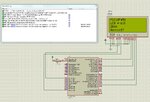
90704d1367919944-4bitlcd.jpg


I got it working in Hi-Tech C Code also but the same problem. "Processor is resetting due to WDT"

Hi-Tech C Code Working, PIC18F458


Code C - [expand]
1
2
3
4
5
6
7
8
9
10
11
12
13
14
15
16
17
18
19
20
21
22
23
24
25
26
27
28
29
30
31
32
33
34
35
36
37
38
39
40
41
42
43
44
45
46
47
48
49
50
51
52
53
54
55
56
57
58
59
60
61
62
63
64
65
66
67
68
69
70
71
72
73
74
75
76
77
78
79
80
81
82
83
84
85
86
87
88
89
90
91
92
93
94
95
96
97
98
99
100
101
102
103
104
105
106
107
108
109
110
111
112
113
114
115
116
117
118
119
120
121
122
123
124
125
126
127
128
129
130
131
132
133
134
135
136
137
138
139
140
141
142
143
144
145
146
147
148
149
150
151
152
153
154
155
156
157
158
159
160
161
162
163
164
165
166
167
168
169
170
171
172
173
174
175
176
177
178
179
180
181
182
183
184
185
186
187
188
189
190
191
192
193
194
195
196
197
198
199
200
201
202
203
204
205
206
207
208
209
210
211
212
213
214
215
216
217
218
219
220
221
222
223
224
225
226
227
228
229
230
231
232
233
234
235
236
237
238
239
240
241
242
243
244
245
246
247
248
249
250
251
252
253
254
255
256
257
258
259
260
261
262
263
264
265
266
267
268
269
270
271
272
273
274
275
276
277
278
279
280
281
282
283
284
285
286
287
288
289
290
291
292
293
294
295
296
297
298
299
300
301
302
303
304
305
306
307
308
309
/*
 * main.c
 *
 * Created: 5/7/2013 9:09:11 AM
 * Author: Jayanth Devarayanadurga
 */ 
 
#include <htc.h>
 
//Define CPU Frequency
//This must be defined, if __delay_ms() or
//__delay_us() functions are used in the code
#define _XTAL_FREQ   4000000
 
// Configuration word for PIC16F877
//__CONFIG( FOSC_HS & WDTE_OFF & PWRTE_ON & CP_OFF & BOREN_ON
//  & LVP_OFF & CPD_OFF & DEBUG_OFF);
 
#define LATA0_bit LATAbits.LATA0
#define LATA1_bit LATAbits.LATA1
#define LATA2_bit LATAbits.LATA2
#define LATA3_bit LATAbits.LATA3
#define LATA4_bit LATAbits.LATA4
#define LATA5_bit LATAbits.LATA5
#define LATA6_bit LATAbits.LATA6
#define LATA7_bit LATAbits.LATA7
#define LATB0_bit LATBbits.LATB0
#define LATB1_bit LATBbits.LATB1
#define LATB2_bit LATBbits.LATB2
#define LATB3_bit LATBbits.LATB3
#define LATB4_bit LATBbits.LATB4
#define LATB5_bit LATBbits.LATB5
#define LATB6_bit LATBbits.LATB6
#define LATB7_bit LATBbits.LATB7
#define LATC0_bit LATCbits.LATC0
#define LATC1_bit LATCbits.LATC1
#define LATC2_bit LATCbits.LATC2
#define LATC3_bit LATCbits.LATC3
#define LATC4_bit LATCbits.LATC4
#define LATC5_bit LATCbits.LATC5
#define LATC6_bit LATCbits.LATC6
#define LATC7_bit LATCbits.LATC7
#define LATD0_bit LATDbits.LATD0
#define LATD1_bit LATDbits.LATD1
#define LATD2_bit LATDbits.LATD2
#define LATD3_bit LATDbits.LATD3
#define LATD4_bit LATDbits.LATD4
#define LATD5_bit LATDbits.LATD5
#define LATD6_bit LATDbits.LATD6
#define LATD7_bit LATDbits.LATD7
 
#define TRISA0_bit TRISAbits.TRISA0
#define TRISA1_bit TRISAbits.TRISA1
#define TRISA2_bit TRISAbits.TRISA2
#define TRISA3_bit TRISAbits.TRISA3
#define TRISA4_bit TRISAbits.TRISA4
#define TRISA5_bit TRISAbits.TRISA5
#define TRISA6_bit TRISAbits.TRISA6
#define TRISB0_bit TRISBbits.TRISB0
#define TRISB1_bit TRISBbits.TRISB1
#define TRISB2_bit TRISBbits.TRISB2
#define TRISB3_bit TRISBbits.TRISB3
#define TRISB4_bit TRISBbits.TRISB4
#define TRISB5_bit TRISBbits.TRISB5
#define TRISB6_bit TRISBbits.TRISB6
#define TRISB7_bit TRISBbits.TRISB7
#define TRISC0_bit TRISCbits.TRISC0
#define TRISC1_bit TRISCbits.TRISC1
#define TRISC2_bit TRISCbits.TRISC2
#define TRISC3_bit TRISCbits.TRISC3
#define TRISC4_bit TRISCbits.TRISC4
#define TRISC5_bit TRISCbits.TRISC5
#define TRISC6_bit TRISCbits.TRISC6
#define TRISC7_bit TRISCbits.TRISC7
#define TRISD0_bit TRISDbits.TRISD0
#define TRISD1_bit TRISDbits.TRISD1
#define TRISD2_bit TRISDbits.TRISD2
#define TRISD3_bit TRISDbits.TRISD3
#define TRISD4_bit TRISDbits.TRISD4
#define TRISD5_bit TRISDbits.TRISD5
#define TRISD6_bit TRISDbits.TRISD6
#define TRISD7_bit TRISDbits.TRISD7
    
#define LCD_RS LATB0_bit
#define LCD_EN LATB7_bit
#define LCD_D4 LATC0_bit
#define LCD_D5 LATC4_bit
#define LCD_D6 LATD3_bit
#define LCD_D7 LATD6_bit
 
#define LCD_RS_Direction TRISB0_bit
#define LCD_EN_Direction TRISB7_bit
#define LCD_D4_Direction TRISC0_bit
#define LCD_D5_Direction TRISC4_bit
#define LCD_D6_Direction TRISD3_bit
#define LCD_D7_Direction TRISD6_bit
 
 
#define _LCD_FIRST_ROW          0x80     //Move cursor to the 1st row
#define _LCD_SECOND_ROW         0xC0     //Move cursor to the 2nd row
#define _LCD_THIRD_ROW          0x94     //Move cursor to the 3rd row
#define _LCD_FOURTH_ROW         0xD4     //Move cursor to the 4th row
#define _LCD_CLEAR              0x01     //Clear display
#define _LCD_RETURN_HOME        0x02     //Return cursor to home position, returns a shifted display to
                                         //its original position. Display data RAM is unaffected.
#define _LCD_CURSOR_OFF         0x0C     //Turn off cursor
#define _LCD_UNDERLINE_ON       0x0E     //Underline cursor on
#define _LCD_BLINK_CURSOR_ON    0x0F     //Blink cursor on
#define _LCD_MOVE_CURSOR_LEFT   0x10     //Move cursor left without changing display data RAM
#define _LCD_MOVE_CURSOR_RIGHT  0x14     //Move cursor right without changing display data RAM
#define _LCD_TURN_ON            0x0C     //Turn Lcd display on
#define _LCD_TURN_OFF           0x08     //Turn Lcd display off
#define _LCD_SHIFT_LEFT         0x18     //Shift display left without changing display data RAM
#define _LCD_SHIFT_RIGHT        0x1E     //Shift display right without changing display data RAM
 
// Constants
#define EN_Delay 500
 
// Give a pulse on E pin
// so that LCD can latch the
// data from data bus
 
#define LCD_STROBE {LCD_EN = 1; __delay_us(EN_Delay); LCD_EN = 0; __delay_us(EN_Delay);};
 
 
//Function Prototypes
void LCD_Cmd(unsigned char Command);
void LCD_Ch(unsigned int row, unsigned int col, char LCDChar);
void LCD_Init();
void LCD_Out(unsigned int row, unsigned int col, const char *str);
 
void LCD_Cmd(unsigned char Command)
{
    LCD_RS = 0;           // It is a command
 
    LCD_D4 = (Command & 0x10)?1:0;
    LCD_D5 = (Command & 0x20)?1:0;
    LCD_D6 = (Command & 0x40)?1:0;
    LCD_D7 = (Command & 0x80)?1:0;
    LCD_STROBE
    LCD_D4 = (Command & 0x01)?1:0;
    LCD_D5 = (Command & 0x02)?1:0;
    LCD_D6 = (Command & 0x04)?1:0;
    LCD_D7 = (Command & 0x08)?1:0;
    LCD_STROBE
 
    if(Command == 0x01)
    __delay_ms(2);              // Delay for cursor to return at zero position
}
 
 
void LCD_Ch(unsigned int row, unsigned int col, char LCDChar)
{
    switch(row){
 
        case 1:
        LCD_Cmd(0x80 + col-1);
        break;
        case 2:
        LCD_Cmd(0xC0 + col-1);
        break;
        case 3:
        LCD_Cmd(0x94 + col-1);
        break;
        case 4:
        LCD_Cmd(0xD4 + col-1);
        break;
    }
 
    LCD_RS = 1;               // It is data
 
    LCD_D4 = (LCDChar & 0x10)?1:0;
    LCD_D5 = (LCDChar & 0x20)?1:0;
    LCD_D6 = (LCDChar & 0x40)?1:0;
    LCD_D7 = (LCDChar & 0x80)?1:0;
    LCD_STROBE
 
    LCD_D4 = (LCDChar & 0x01)?1:0;
    LCD_D5 = (LCDChar & 0x02)?1:0;
    LCD_D6 = (LCDChar & 0x04)?1:0;
    LCD_D7 = (LCDChar & 0x08)?1:0;
    LCD_EN = 1;
    LCD_STROBE
}
 
 
void LCD_Init()
{
    LCD_RS = 0;
    LCD_EN = 0; 
    LCD_D4 = 0;
    LCD_D5 = 0;
    LCD_D6 = 0;
    LCD_D7 = 0;
    LCD_RS_Direction = 0;
    LCD_EN_Direction = 0;
    LCD_D4_Direction = 0;
    LCD_D5_Direction = 0;
    LCD_D6_Direction = 0;
    LCD_D7_Direction = 0;   
    
    ///////////////// Reset process from datasheet //////////////
    __delay_ms(30);
 
    //Make Data pins zero
    
    LCD_D4 = 0;
    LCD_D5 = 0;
    LCD_D6 = 0;
    LCD_D7 = 0;
    
    //Write 0x3 value on data bus
    LCD_D4 = 1;
    LCD_D5 = 1;
    LCD_D6 = 0;
    LCD_D7 = 0;
 
    LCD_STROBE
 
    __delay_ms(6);
 
    //Make Data pins zero
    
    LCD_D4 = 0;
    LCD_D5 = 0;
    LCD_D6 = 0;
    LCD_D7 = 0;
 
    //Write 0x3 value on data bus
    LCD_D4 = 1;
    LCD_D5 = 1;
    LCD_D6 = 0;
    LCD_D7 = 0;
 
    LCD_STROBE
 
    __delay_ms(3);
 
    //Make Data pins zero
    
    LCD_D4 = 0;
    LCD_D5 = 0;
    LCD_D6 = 0;
    LCD_D7 = 0;
 
    //Write 0x3 value on data bus
    LCD_D4 = 1;
    LCD_D5 = 1;
    LCD_D6 = 0;
    LCD_D7 = 0;
 
    LCD_STROBE
 
    __delay_ms(2);
 
    //Make Data pins zero
    
    LCD_D4 = 0;
    LCD_D5 = 0;
    LCD_D6 = 0;
    LCD_D7 = 0;
 
    //Write 0x2 value on data bus
    LCD_D4 = 0;
    LCD_D5 = 1;
    LCD_D6 = 0;
    LCD_D7 = 0;
 
    LCD_STROBE
 
    __delay_ms(2);
    /////////////// Reset Process End ////////////////
    LCD_Cmd(0x28);    //function set
    LCD_Cmd(0x0C);    //display on,cursor off,blink off
    LCD_Cmd(0x06);    //entry mode, set increment
}
 
void LCD_Out(unsigned int row, unsigned int col, const char *str)
{
    while(*str)
    LCD_Ch(row,col++,*str++);   // print first character on LCD
    row = 1;
    col = 1;
}
 
int main(void){
 
    TRISA = 0x00;
    TRISB = 0x00;
    TRISC = 0x00;
    TRISD = 0x00;
    LATA = 0x00;
    LATB = 0x00;
    LATC = 0x00;
    LATD = 0x00;
 
    LCD_Init();
    LCD_Cmd(_LCD_CLEAR);
    LCD_Cmd(_LCD_CURSOR_OFF);
 
    LCD_Out(1,1,"PIC18F458");
    LCD_Out(2,1,"LCD 4-bit");
    LCD_Out(3,1,"20X4");
    LCD_Out(4,1,"Working?");
 
    while(1);
 
    return (0);
}


I changed the config code like this but still the same error.


Code C - [expand]
1
2
#pragma CONFIG1 WDTE_OFF
#pragma CONFIG1 FOSC_XT


Attachments

  • XC8_LCD_4bit_PIC18F458_4MHz.rar
    323 KB · Views: 133
  • 4bitlcd.jpg
    4bitlcd.jpg
    310.3 KB · Views: 255
  • mplabhitechclcd4bitpinaddr.rar
    141.2 KB · Views: 180
Last edited:

5489159900_1367921256.png

Code:
#include <pic.h>               //test
#define _XTAL_FREQ 20000000
    
#define LCD_RS RC0
#define LCD_EN RC1

#define LCD_D4 RB7
#define LCD_D5 RC6
#define LCD_D6 RD0
#define LCD_D7 RD7
 
 
#define _LCD_FIRST_ROW          0x80     //Move cursor to the 1st row
#define _LCD_SECOND_ROW         0xC0     //Move cursor to the 2nd row
#define _LCD_THIRD_ROW          0x94     //Move cursor to the 3rd row
#define _LCD_FOURTH_ROW         0xD4     //Move cursor to the 4th row
#define _LCD_CLEAR              0x01     //Clear display
#define _LCD_RETURN_HOME        0x02     //Return cursor to home position, returns a shifted display to
                                         //its original position. Display data RAM is unaffected.
#define _LCD_CURSOR_OFF         0x0C     //Turn off cursor
#define _LCD_UNDERLINE_ON       0x0E     //Underline cursor on
#define _LCD_BLINK_CURSOR_ON    0x0F     //Blink cursor on
#define _LCD_MOVE_CURSOR_LEFT   0x10     //Move cursor left without changing display data RAM
#define _LCD_MOVE_CURSOR_RIGHT  0x14     //Move cursor right without changing display data RAM
#define _LCD_TURN_ON            0x0C     //Turn Lcd display on
#define _LCD_TURN_OFF           0x08     //Turn Lcd display off
#define _LCD_SHIFT_LEFT         0x18     //Shift display left without changing display data RAM
#define _LCD_SHIFT_RIGHT        0x1E     //Shift display right without changing display data RAM
 
// Constants
#define EN_Delay 500
 
// Give a pulse on E pin
// so that LCD can latch the
// data from data bus
 
#define LCD_STROBE LCD_EN = 1; __delay_us(EN_Delay); LCD_EN = 0; __delay_us(EN_Delay);
 
 
//Function Prototypes
void LCD_Cmd(unsigned char Command);
void LCD_Ch(unsigned int row, unsigned int col, char LCDChar);
void LCD_Init();
void LCD_Out(unsigned int row, unsigned int col, const char *str);
 
void LCD_Cmd(unsigned char Command)
{
    LCD_RS = 0;           // It is a command
 
    LCD_D4 = (Command & 0x10)?1:0;
    LCD_D5 = (Command & 0x20)?1:0;
    LCD_D6 = (Command & 0x40)?1:0;
    LCD_D7 = (Command & 0x80)?1:0;
    
    LCD_STROBE;
    LCD_D4 = (Command & 0x01)?1:0;
    LCD_D5 = (Command & 0x02)?1:0;
    LCD_D6 = (Command & 0x04)?1:0;
    LCD_D7 = (Command & 0x08)?1:0;
    
    LCD_STROBE;
 
    if(Command == 0x01)  __delay_ms(2);              // Delay for cursor to return at zero position
}
 
 
void LCD_Ch(unsigned int row, unsigned int col, char LCDChar)
{
    switch(row)
	    {
 
        case 1:
        LCD_Cmd(0x80 + col-1);
        break;
        case 2:
        LCD_Cmd(0xC0 + col-1);
        break;
        case 3:
        LCD_Cmd(0x94 + col-1);
        break;
        case 4:
        LCD_Cmd(0xD4 + col-1);
        break;
    }
 
    LCD_RS = 1;               // It is data
 
    LCD_D4 = (LCDChar & 0x10)?1:0;
    LCD_D5 = (LCDChar & 0x20)?1:0;
    LCD_D6 = (LCDChar & 0x40)?1:0;
    LCD_D7 = (LCDChar & 0x80)?1:0;
    
    LCD_STROBE;
 
    LCD_D4 = (LCDChar & 0x01)?1:0;
    LCD_D5 = (LCDChar & 0x02)?1:0;
    LCD_D6 = (LCDChar & 0x04)?1:0;
    LCD_D7 = (LCDChar & 0x08)?1:0;
    LCD_EN = 1;
    
    LCD_STROBE;
}
 
 
void LCD_Init()
{

       LCD_EN=0;
       LCD_RS=0;
       __delay_us(100); 
       
LCD_D4 = 1;
LCD_D5 = 1;
LCD_D6 = 0;
LCD_D7 = 0;  
      
//	LCD=0X30;
	
     	 LCD_STROBE;
     	 
       	__delay_ms(2);

       LCD_RS=0;
    
LCD_D4 = 1;
LCD_D5 = 1;
LCD_D6 = 0;
LCD_D7 = 0;          
       
//	LCD=0X30;
     	 LCD_STROBE;
     	 
	__delay_ms(2);

        LCD_RS=0;
//	LCD=0X30;

LCD_D4 = 1;
LCD_D5 = 1;
LCD_D6 = 0;
LCD_D7 = 0;   

       	 LCD_STROBE;
       	 
	__delay_ms(2);
	
       LCD_RS=0;
       
LCD_D4 = 0;
LCD_D5 = 1;
LCD_D6 = 0;
LCD_D7 = 0;         
       
       
//	LCD=0X20;
     	 LCD_STROBE;
     	 
	__delay_ms(2);

	LCD_Cmd(0X28);
	__delay_ms(5);
	LCD_Cmd(0X0C);
	__delay_ms(5);
	LCD_Cmd(0X01);
	__delay_ms(5);
	LCD_Cmd(0X06);
	__delay_ms(5);
}
 
void LCD_Out(unsigned int row, unsigned int col, const char *str)
{
    while(*str)
    LCD_Ch(row,col++,*str++);   // print first character on LCD
    row = 1;
    col = 1;
}
 
int main(void)
	{
 unsigned char data;
    TRISA = 0x00;  TRISB = 0x00; TRISC = 0x00; TRISD = 0x00;  

 
    LCD_Init();
    LCD_Cmd(_LCD_CLEAR);
    LCD_Cmd(_LCD_CURSOR_OFF);


    LCD_Out(1,1,"PIC18F458");
    LCD_Out(2,1,"LCD 4-bit");
    LCD_Out(3,1,"20X4");
    LCD_Out(4,1,"Working?"); 


    while(1);
 
    return (0);
}
 
Justin did you fix the processor resetting due to WDT?

Disabling WDT in Proteus make it work fine in Proteus. Time to test it in real hardware... :cool:


Edit:

Working beautifully in hardware... :cool:

Code for AT89C52


Code C - [expand]
1
2
3
4
5
6
7
8
9
10
11
12
13
14
15
16
17
18
19
20
21
22
23
24
25
26
27
28
29
30
31
32
33
34
35
36
37
38
39
40
41
42
43
44
45
46
47
48
49
50
51
52
53
54
55
56
57
58
59
60
61
62
63
64
65
66
67
68
69
70
71
72
73
74
75
76
77
78
79
80
81
82
83
84
85
86
87
88
89
90
91
92
93
94
95
96
97
98
99
100
101
102
103
104
105
106
107
108
109
110
111
112
113
114
115
116
117
118
119
120
121
122
123
124
125
126
127
128
129
130
131
132
133
134
135
136
137
138
139
140
141
142
143
144
145
146
147
148
149
150
151
152
153
154
155
156
157
158
159
160
161
162
163
164
165
166
167
168
169
170
171
172
173
174
175
176
177
178
179
180
181
182
183
184
185
186
187
188
189
190
191
192
193
194
195
196
197
198
199
200
201
202
203
204
205
206
207
208
209
210
211
212
/*
 * main.c
 *
 * Created: 5/7/2013 9:09:11 AM
 * Author: Jayanth Devarayanadurga
 */
 
#define LCD_RS P2_0_bit
#define LCD_EN P2_1_bit
#define LCD_D4 P2_2_bit
#define LCD_D5 P2_7_bit
#define LCD_D6 P3_0_bit
#define LCD_D7 P3_3_bit
 
#define _LCD_FIRST_ROW          0x80     //Move cursor to the 1st row
#define _LCD_SECOND_ROW         0xC0     //Move cursor to the 2nd row
#define _LCD_THIRD_ROW          0x94     //Move cursor to the 3rd row
#define _LCD_FOURTH_ROW         0xD4     //Move cursor to the 4th row
#define _LCD_CLEAR          0x01     //Clear display
#define _LCD_RETURN_HOME        0x02     //Return cursor to home position, returns a shifted display to
                                         //its original position. Display data RAM is unaffected.
#define _LCD_CURSOR_OFF         0x0C     //Turn off cursor
#define _LCD_UNDERLINE_ON       0x0E     //Underline cursor on
#define _LCD_BLINK_CURSOR_ON            0x0F     //Blink cursor on
#define _LCD_MOVE_CURSOR_LEFT           0x10     //Move cursor left without changing display data RAM
#define _LCD_MOVE_CURSOR_RIGHT          0x14     //Move cursor right without changing display data RAM
#define _LCD_TURN_ON            0x0C     //Turn Lcd display on
#define _LCD_TURN_OFF           0x08     //Turn Lcd display off
#define _LCD_SHIFT_LEFT         0x18     //Shift display left without changing display data RAM
#define _LCD_SHIFT_RIGHT        0x1E     //Shift display right without changing display data RAM
 
// Constants
#define EN_Delay 500
 
// Give a pulse on E pin
// so that LCD can latch the
// data from data bus
 
#define LCD_STROBE {LCD_EN = 1; Delay_us(EN_Delay); LCD_EN = 0; Delay_us(EN_Delay);};
 
 
//Function Prototypes
void LCD_Cmd(unsigned char Command);
void LCD_Ch(unsigned int row, unsigned int col, char LCDChar);
void LCD_Init();
void LCD_Out(unsigned int row, unsigned int col, const char *str);
 
void LCD_Cmd(unsigned char Command)
{
    LCD_RS = 0;           // It is a command
 
    LCD_D4 = (Command & 0x10)?1:0;
    LCD_D5 = (Command & 0x20)?1:0;
    LCD_D6 = (Command & 0x40)?1:0;
    LCD_D7 = (Command & 0x80)?1:0;
    LCD_STROBE;
    LCD_D4 = (Command & 0x01)?1:0;
    LCD_D5 = (Command & 0x02)?1:0;
    LCD_D6 = (Command & 0x04)?1:0;
    LCD_D7 = (Command & 0x08)?1:0;
    LCD_STROBE;
 
    if(Command == 0x01)
    Delay_ms(2);              // Delay for cursor to return at zero position
}
 
 
void LCD_Ch(unsigned int row, unsigned int col, char LCDChar)
{
    switch(row){
 
        case 1:
        LCD_Cmd(0x80 + col-1);
        break;
        case 2:
        LCD_Cmd(0xC0 + col-1);
        break;
        case 3:
        LCD_Cmd(0x94 + col-1);
        break;
        case 4:
        LCD_Cmd(0xD4 + col-1);
        break;
    }
 
    LCD_RS = 1;               // It is data
 
    LCD_D4 = (LCDChar & 0x10)?1:0;
    LCD_D5 = (LCDChar & 0x20)?1:0;
    LCD_D6 = (LCDChar & 0x40)?1:0;
    LCD_D7 = (LCDChar & 0x80)?1:0;
    LCD_STROBE;
 
    LCD_D4 = (LCDChar & 0x01)?1:0;
    LCD_D5 = (LCDChar & 0x02)?1:0;
    LCD_D6 = (LCDChar & 0x04)?1:0;
    LCD_D7 = (LCDChar & 0x08)?1:0;
    LCD_EN = 1;
    LCD_STROBE;
}
 
 
void LCD_Init()
{
    LCD_RS = 0;
    LCD_EN = 0;
    LCD_D4 = 0;
    LCD_D5 = 0;
    LCD_D6 = 0;
    LCD_D7 = 0;
 
    ///////////////// Reset process from datasheet //////////////
    Delay_ms(30);
 
    //Make Data pins zero
 
    LCD_D4 = 0;
    LCD_D5 = 0;
    LCD_D6 = 0;
    LCD_D7 = 0;
 
    //Write 0x3 value on data bus
    LCD_D4 = 1;
    LCD_D5 = 1;
    LCD_D6 = 0;
    LCD_D7 = 0;
 
    LCD_STROBE;
 
    Delay_ms(6);
 
    //Make Data pins zero
 
    LCD_D4 = 0;
    LCD_D5 = 0;
    LCD_D6 = 0;
    LCD_D7 = 0;
 
    //Write 0x3 value on data bus
    LCD_D4 = 1;
    LCD_D5 = 1;
    LCD_D6 = 0;
    LCD_D7 = 0;
 
    LCD_STROBE;
 
    Delay_ms(3);
 
    //Make Data pins zero
 
    LCD_D4 = 0;
    LCD_D5 = 0;
    LCD_D6 = 0;
    LCD_D7 = 0;
 
    //Write 0x3 value on data bus
    LCD_D4 = 1;
    LCD_D5 = 1;
    LCD_D6 = 0;
    LCD_D7 = 0;
 
    LCD_STROBE;
 
    Delay_ms(2);
 
    //Make Data pins zero
 
    LCD_D4 = 0;
    LCD_D5 = 0;
    LCD_D6 = 0;
    LCD_D7 = 0;
 
    //Write 0x2 value on data bus
    LCD_D4 = 0;
    LCD_D5 = 1;
    LCD_D6 = 0;
    LCD_D7 = 0;
 
    LCD_STROBE;
 
    Delay_ms(2);
    /////////////// Reset Process End ////////////////
    LCD_Cmd(0x28);    //function set
    LCD_Cmd(0x0C);    //display on,cursor off,blink off
    LCD_Cmd(0x06);    //entry mode, set increment
}
 
void LCD_Out(unsigned int row, unsigned int col, const char *str)
{
    while(*str)
    LCD_Ch(row,col++,*str++);   // print first character on LCD
    row = 1;
    col = 1;
}
 
void main(){
 
    P0 = 0x00;
    P1 = 0x00;
    P2 = 0x00;
    P3 = 0x00;
    
    LCD_Init();
    LCD_Cmd(_LCD_CLEAR);
    LCD_Cmd(_LCD_CURSOR_OFF);
    LCD_Out(1,1,"AT89C52");
    LCD_Out(2,1,"LCD 4-bit");
    LCD_Out(3,1,"20X4");
    LCD_Out(4,1,"Working?");
 
    while(1);
}


90711d1367924495-lcd4bit.jpg


AVR Studio 4.19 Code here... https://www.edaboard.com/threads/287961/
Atmel Studio 6.0 Code attached.
 

Attachments

  • AT89C52_LCD_4bit.rar
    142.8 KB · Views: 139
  • lcd4bit.jpg
    lcd4bit.jpg
    195.7 KB · Views: 249
  • ats60lcd4bit.rar
    59.9 KB · Views: 135
Last edited:

Status
Not open for further replies.

Similar threads

Part and Inventory Search

Welcome to EDABoard.com

Sponsor

Back
Top