Continue to Site

Welcome to EDAboard.com

Welcome to our site! EDAboard.com is an international Electronics Discussion Forum focused on EDA software, circuits, schematics, books, theory, papers, asic, pld, 8051, DSP, Network, RF, Analog Design, PCB, Service Manuals... and a whole lot more! To participate you need to register. Registration is free. Click here to register now.

Design Halfband filter with matlab for interpolation

Status
Not open for further replies.

nhkch

Junior Member level 2
Joined
Jan 21, 2013
Messages
21
Helped
0
Reputation
0
Reaction score
0
Trophy points
1,281
Activity points
1,411
hbf_pdf.PNG


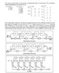
I'm trying to design a half band filter for interpolation used in Sigma delta modulator. Current using Matlab delsig toolbox by Richard Schreier..

There is a function designHBF. I try the example given and got the result as stated in the pdf which is the snap shot below. I cant understand how to connect the value obtain with the diagram given. What is the switch at the end of the filter in interpolation structure (out@fs) mean? Anyone can help? thanks
 

It means that for one input sample you have two output samples, i.e. interpolation.
 

Hi Mityan, can you further elaborate your statement because i not really get how the two output connected with interpolation. Thanks in advance.
 

they are just switching with the double fs rate.
Look, the bottom of the interpolation structure picture is just a delay line that outputs direct input samples. The top branch of processing represents the interpolation, which inserts samples between input so as to get double output rate.
 
  • Like
Reactions: nhkch

    nhkch

    Points: 2
    Helpful Answer Positive Rating
I see..but if the top branch is already the interpolation process..why is the switch at double input rate still needed?
 

Top branch is just a shift register. It works at input rate.
And what rate are you waiting at the output?
And what the interpolated samples should be placed between?
 

my input sampling frequency is 41khz and would like to upsampling it to 82khz....so at the output (out@fs), should i implement a switch that switching at the frequency of 82khz for the upsampling purpose?

What do you mean by " what the interpolated samples should be placed between?
 

my input sampling frequency is 41khz and would like to upsampling it to 82khz....so at the output (out@fs), should i implement a switch that switching at the frequency of 82khz for the upsampling purpose?

What do you mean by " what the interpolated samples should be placed between?

I meant between what - between input samples. between input samples that have 41kHz rate you place interpolated samples by switching the switch at 82.
 

In digital, 41khz give me 4sample..eg 1011....after going through 82khz...it become 8sample which is 11011110 right?
 

Status
Not open for further replies.

Similar threads

Part and Inventory Search

Welcome to EDABoard.com

Sponsor

Back
Top