Continue to Site

Welcome to EDAboard.com

Welcome to our site! EDAboard.com is an international Electronics Discussion Forum focused on EDA software, circuits, schematics, books, theory, papers, asic, pld, 8051, DSP, Network, RF, Analog Design, PCB, Service Manuals... and a whole lot more! To participate you need to register. Registration is free. Click here to register now.

MICROC prgramming help needed for blinking led project.

Status
Not open for further replies.

peter_england

Full Member level 4
Full Member level 4
Joined
Jul 24, 2012
Messages
199
Helped
11
Reputation
22
Reaction score
11
Trophy points
1,298
Activity points
2,478
please help i am using following code with microc ide and proteus for simulation .. after compiling following code and uploading hex file to simulation nothing happens to pic16f676

===============================CODE===============================

void main(void) {

TRISc.Rc3 = 0x00;
while(1);{
PORTc.RC3 = 1;
delay_ms(500);
PORTc.RC3 = 0;
delay_ms(500);
}
}

===============================CODE================================

PLEASE tell someone what is going wrong in this ???
 

i dont work on microc. but if you rnt getting a syntax error in PORTc.RC3 etc (as u haven't followed a particular standard of upper or lower case), thn just remove the semicolon in the while line. semicolon will result in unreachable code next to while.

void main(void)
{
TRISc.Rc3 = 0x00;
while(1)
{
PORTc.RC3 = 1;
delay_ms(500);
PORTc.RC3 = 0;
delay_ms(500);
}
}
 
still no success, the code compiles with no errors but not simulating as expected ..
 

Check the fuses!!!! CTRL + SHIFT + E!!!

Here works fine into isis using 16MHz crystal osc on RA4+RA5 (you can use internal rc osc)!!!

Added project!!!

With and without crystal osc!!!
 

Attachments

  • Test 01.rar
    14.9 KB · Views: 114
  • Test 02 (No XT).rar
    14.9 KB · Views: 99
Last edited:
I think you are a beginner

proteus works without config setting of oscillators.
okay so problem is with your project.
check whether you had added the file properly and created the project properly.
as this is the most common mistake a newbie do.

so check that.
and if problem still persist zip your project alonh with simulation file and attach it here.
i will correct it and will tell you your mistake.
dont worry
 
Try this code it will work. Remember to pullup MCLR pin high through a 10k resistor.

Code C - [expand]
1
2
3
4
5
6
7
8
9
10
11
12
void main(void) 
{
    TRISC.F3 = 0x00;
    PORTC.F3 = 0x00;
    while(1)
    {
        PORTC.F3 = 1;
        Delay_ms(500);
        PORTC.F3 = 0;
        Delay_ms(500);
    }
}

 
Check the fuses!!!! CTRL + SHIFT + E!!!

Here works fine into isis using 16MHz crystal osc on RA4+RA5 (you can use internal rc osc)!!!

Added project!!!

With and without crystal osc!!!

your project is working fine and i only made one wrong setting is that mclr is on in my project and in yours is off /disable after that editing in project properties its working fine ... thanks for help.
 

Yes!!!
I always I take the MCLR to be used as input, even if he is not used!!!
Me and my habits!!!
Hehehe...
 

please help i am using following code with microc ide and proteus for simulation .. after compiling following code and uploading hex file to simulation nothing happens to pic16f676

===============================CODE===============================

void main(void) {

TRISc.Rc3 = 0x00;
while(1);{
PORTc.RC3 = 1;
delay_ms(500);
PORTc.RC3 = 0;
delay_ms(500);
}
}

===============================CODE================================

PLEASE tell someone what is going wrong in this ???

Your program execution is stuck because there is a semicolon after the while(1).

Remove it.

And make sure your learn from this common error for C noobs. :wink:
 

Hi everyone,

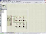
I hope you guys can guide and teach me a lots in microcontroller works. I want to try out this project by peter_england.
I want to do the project Controlled LED with push button, and interface it with PIC which is PIC16F877A.

Can I have your favor on checking my schematic and especially in C code. Im using the microC compiler too.
LED+ Switch.JPG

Code:
/*
    Project Title: Controled LED by switches
  
*/

void main()
{
  TRISA=0B11111111; //Configure all bit of PORTA as input
  TRISB=0B00000000; //Configure all bit of PORTB as output
   

while (1);
{
    if( TRISA.F0 == 0)   //If the switch is pressed
       {

         PORTB.F0 = ~PORTB.F0;   // Toggle LEDs on PORTB.0
         Delay_ms(1000);         // Delay 1000 ms

       }
    else
    if (TRISA.F1 == 0)   //If the switch is pressed
       {
        
        PORTB.F1 = ~PORTB.F1;       // Toggle LEDs on PORTB.1
        Delay_ms(1000);           // Delay 1000 ms

       }
    else
    if(TRISA.F2 == 0)   //If the switch is pressed
       {

        PORTB.F2 = ~PORTB.F2;       // Toggle LEDs on PORTB.2
        Delay_ms(1000);           // Delay 1000 ms

       }
    else
    if(TRISA.F3 == 0)   //If the switch is pressed
       {
        
        PORTB.F3 = ~PORTB.F3;       // Toggle LEDs on PORTB.3
        Delay_ms(1000);           // Delay 1000 ms

       }
    else
    if(TRISA.F4 == 0)   //If the switch is pressed
       {

        PORTB.F4 = ~PORTB.F4;       // Toggle LEDs on PORTB.4
        Delay_ms(1000);           // Delay 1000 ms

       }
    else
    if(TRISA.F5 == 0)   //If the switch is pressed
       {

        PORTB.F5 = ~PORTB.F5;       // Toggle LEDs on PORTB.5
        Delay_ms(1000);           // Delay 1000 ms

       }

 }


}

I would appreciate your reply in advance.

Thanks.
 

You should replace testing for 0 in all if condition with testing for 1 like if( TRISA.F0 == 0) should be if( TRISA.F0 == 1) as pins become high when button is pressed. You have to add debounce delays to all switches like


Code C - [expand]
1
2
3
4
5
6
7
if( TRISA.F0 == 1)   //If the switch is pressed
       {
 
         PORTB.F0 = ~PORTB.F0;   // Toggle LEDs on PORTB.0
         Delay_ms(1000);         // Delay 1000 ms
 
       }


should be


Code C - [expand]
1
2
3
4
5
6
7
8
9
10
if( TRISA.F0 == 1)   //If the switch is pressed
       {
          Delay_ms(30);
          if( TRISA.F0 == 1)   //If the switch is pressed
       {
 
         PORTB.F0 = ~PORTB.F0;   // Toggle LEDs on PORTB.0
         Delay_ms(1000);         // Delay 1000 ms
          }
       }


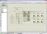
Thanks Jayanth for the reply. But I still got problem in my isis simulation, where all LED are ON simultaneously after i click the run button.


result.JPG

Here is the code after edit.

Code:
/*
    Project Title: Controled LED by switches

*/

void main()
{
  TRISA=0B11111111; //Configure all bit of PORTA as input
  TRISB=0B00000000; //Configure all bit of PORTB as output


while (1);
{
    if( TRISA.F0 == 1)   //If the switch is pressed
       {
          {
          Delay_ms(30);
          if( TRISA.F0 == 1)   //If the switch is pressed

          PORTB.F0 = ~PORTB.F0;   // Toggle LEDs on PORTB.0
          Delay_ms(1000);         // Delay 1000 ms
          }
       }
    else
    if (TRISA.F1 == 1)   //If the switch is pressed
       {
          {
          Delay_ms(30);
          if( TRISA.F1 == 1)   //If the switch is pressed

          PORTB.F1 = ~PORTB.F0;   // Toggle LEDs on PORTB.1
          Delay_ms(1000);         // Delay 1000 ms
          }
       }
    else
    if(TRISA.F2 == 1)   //If the switch is pressed
       {
          {
          Delay_ms(30);
          if( TRISA.F2 == 1)   //If the switch is pressed

          PORTB.F2 = ~PORTB.F0;   // Toggle LEDs on PORTB.2
          Delay_ms(1000);         // Delay 1000 ms
          }
       }
    else
    if(TRISA.F3 == 1)   //If the switch is pressed
       {
          {
          Delay_ms(30);
          if( TRISA.F3 == 1)   //If the switch is pressed

          PORTB.F3 = ~PORTB.F0;   // Toggle LEDs on PORTB.3
          Delay_ms(1000);         // Delay 1000 ms
          }
       }
    else
    if(TRISA.F4 == 1)   //If the switch is pressed
       {
          {
          Delay_ms(30);
          if( TRISA.F4 == 1)   //If the switch is pressed

          PORTB.F4 = ~PORTB.F4;   // Toggle LEDs on PORTB.4
          Delay_ms(1000);         // Delay 1000 ms
          }
       }
    else
    if(TRISA.F5 == 1)   //If the switch is pressed
       {
          {
          Delay_ms(30);
          if( TRISA.F5 == 1)   //If the switch is pressed

          PORTB.F5 = ~PORTB.F5;   // Toggle LEDs on PORTB.0
          Delay_ms(1000);         // Delay 1000 ms
          }
       }

 }


}


You have to add debounce delays to all switches.


Should I add debounce switch in my circuit?
 

From each pin of PORTA connect 10K resistor to Ground.

Code C - [expand]
1
2
3
4
5
6
7
8
9
10
11
12
13
14
15
16
17
18
19
20
21
22
23
24
25
26
27
28
29
void main(){
    
    unsigned char led1flag = 0; 
 
    TRISA = 0xFF;
    TRISB = 0x00;
    PORTA = 0x00;
    PORTB = 0x00;
 
    while(1){
 
 
        if(TRISA.F0){
            Delay_ms(30);
            if(TRISA.F0){
                ledflag = ~ledflag;
            }       
        }
 
        if(ledflag){
 
            PORTB.F0 = ~PORTB.F0;
            Delay_ms(1000);
        }
        else if(!ledflag){
            PORTB.F0 = 0;
        }
    }
]


From each pin of PORTA connect 10K resistor to Ground.

Here is the circuit after edit.
result 2.JPG


TRISA = 0xFF;
TRISB = 0x00;
PORTA = 0x00;
PORTB = 0x00;


Sorry, what the different TRIS and PORT actually? I got confuse when you configure all bits as input (TRISA = 0xFF;) then change all bits to output (PORTA = 0x00;)

and I need your favor to put the comment so that I will easy to learn.

Thanks.
 

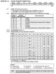
Circuit is ok. TRISx is used to set direction of PORT i.e., input or output. TRISA = 0b11111111 is equal to TRISA = 0xFF;. TRISA = )FF makes all PORTA pins input and TRISA = 0x00 makes all PORTA pins output. PORTA = 0x00 clears the PORT initially. PORTA of PIC16F877A has ADC and Comparator functions. You have to set ADCON1 and CMCON registers for PORTA to work as digital input pins. CMCON = 0x07; and for ADCON1 see datasheet ADC section - ADCON1 register settings. In the table D represents digital. Choose the setting which makes all PORTA pins D (Digital).
 

PORTA of PIC16F877A has ADC and Comparator functions. You have to set ADCON1 and CMCON registers for PORTA to work as digital input pins. CMCON = 0x07; and for ADCON1 see datasheet ADC section - ADCON1 register settings. In the table D represents digital. Choose the setting which makes all PORTA pins D (Digital).

Code:
 TRISA=0XFF; //Configure all bit of PORTA as input
  TRISB=0X00; //Configure all bit of PORTB as output
  PORTA=0X00;       // Clear bits to zero
  PORTB=0X00;       // Clear bits to zero
  
  CMCON=0X07; //      or CMCON register = 0X00000111
  
  ADCON1=0X07; //     Configure ADCON1, or ADCON1=0X06;

adcon1.JPG

this table right? I still did not understand to used it...
 

Status
Not open for further replies.

Part and Inventory Search

Welcome to EDABoard.com

Sponsor

Back
Top