Continue to Site

Welcome to EDAboard.com

Welcome to our site! EDAboard.com is an international Electronics Discussion Forum focused on EDA software, circuits, schematics, books, theory, papers, asic, pld, 8051, DSP, Network, RF, Analog Design, PCB, Service Manuals... and a whole lot more! To participate you need to register. Registration is free. Click here to register now.

ADC Value Fluctuating in PIC Voltmeter and Ammeter LCD PIC16F877A

Status
Not open for further replies.

asking

Full Member level 5
Full Member level 5
Joined
Sep 21, 2010
Messages
279
Helped
6
Reputation
12
Reaction score
6
Trophy points
1,298
Activity points
3,377
Hello,

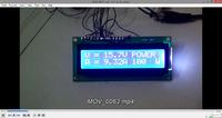
I tried to made Digital Voltmeter and Ammeter
Here's the Circuit diagram


Problem's M Facing:-

1) Voltage and Current both values fluctuating..constantly...

2) Not measuring the voltage or currrent...values...

Question...

Can we place crystal below the microncontroller ? will it affect its operation ? (photo below)
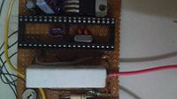


Please help.....

Code:
// LCD module connections
sbit LCD_RS at RB5_bit;
sbit LCD_EN at RB7_bit;
sbit LCD_D4 at RC4_bit;
sbit LCD_D5 at RC5_bit;
sbit LCD_D6 at RC6_bit;
sbit LCD_D7 at RC7_bit;

sbit LCD_RS_Direction at TRISB5_bit;
sbit LCD_EN_Direction at TRISB7_bit;
sbit LCD_D4_Direction at TRISC4_bit;
sbit LCD_D5_Direction at TRISC5_bit;
sbit LCD_D6_Direction at TRISC6_bit;
sbit LCD_D7_Direction at TRISC7_bit;
// End LCD module connections

unsigned int v,vp,ip,i,volt1,current1, PWR;


char look(int a)
{
   switch(a)
   {
       case 0:
              return '0';
       case 1:
              return '1';
       case 2:
              return '2';
       case 3:
              return '3';
       case 4:
              return '4';
       case 5:
              return '5';
       case 6:
              return '6';
       case 7:
              return '7';
       case 8:
              return '8';
       case 9:
              return '9';
       default:
              return '.';
   }
}


void main()
{


  char *volt = "00.0";
  char *current = "0.00";
  TRISA  = 0xFF;
  volt1 = volt;
  current1 = current;
  Lcd_Init();
  Lcd_Cmd(_LCD_CLEAR);
  Lcd_Cmd(_LCD_CURSOR_OFF);

  do
  {

       ADCON1 = 0x00;
       v = ADC_Read(2);
       i = ADC_Read(3);
       i = (i*4.89)/0.47;
       v = ((v*4.89)/20)*120;
       if(v!=vp || i!=ip )
          Lcd_Cmd(_LCD_CLEAR);
       vp = v;
       ip = i;
       PWR = v*i;
       volt[0] = look(v/10000);
       volt[1] = look((v/1000)%10);
       volt[3] = look((v/100)%10);
       Lcd_Out(1,1,"V = ");
       Lcd_Out(1,5,volt);
       Lcd_Out(1,9,"V");
       Lcd_Out(1,11,"POWER");

       current[0] = look(i/1000);
       current[2] = look((i/100)%10);
       current[3] = look((i/10)%10);
       Lcd_Out(2,1,"A = ");
       Lcd_Out(2,5,current);
       Lcd_Out(2,9,"A");
       

       Lcd_Out(2,1,"A = ");
       Lcd_Out(2,11,"hello");
       Lcd_Out(2,16,"W");


       Delay_ms(300);

       
  } while(1);
}
 

The fluctuating could be casued by noise in circuit, Try placing a 10uF cap on the input of the pin your measuring (RA0) of the micro. I've always place the crystal on the outside never seen mounted like picutre not sure what effect this would have but I would say it's more noise related
 

Thanks.... but i think in my case it would be RA4 right ? so you mean to say i should connect 10uf electrolytic capacitor +ve to RA4 and -ve to ground right ?
 

Looking at your schematic your voltage reading goes to RA2,so connect the 10uF + to pin 4(RA2) - to gnd, Also looking at your schecmatic I see your using 22k and 100K, I think this would be better R1 36K and R2 4K7 as the data sheet explains not to take it higer than 10K input , I dont like using zener diodes on the input thay can effect your readings also generate extra noise with R1= 36K &R2= 4K7 with 35 volts input you get 4.042 volts out so no need for zener diode and the same for D2 not needed, Can't understand why you need R3 if your using .47 (470R) resistor then the V drop accross would be 4.699999volts at 10 amps if the resistor is meant to be a .047R then at 10amps it would be 470 millivolts.
 
  • Like
Reactions: asking

    asking

    Points: 2
    Helpful Answer Positive Rating
I notice that you are measuring a current in excess of 9A. But the wires from the large resistor (which I assume is the sense / shunt resistor) are quite "thin". If the wires and resistor heat up, their resistances will change. This will cause an error in your current reading.

Regarding the stability issues, place a 1k resistor in series between the input to the PIC and the PIC ADC pin. Place a 0.1uF ceramic capacitor from the ADC pin to ground. See if that helps things. Like mentioned before, it does seem like a noise-related issue.

Hope this helps.
Tahmid.
 
  • Like
Reactions: asking

    asking

    Points: 2
    Helpful Answer Positive Rating
I tried to put 33pf capacitor across the ADC pin and Ground but did nothing....i think...can Soldering Flux can affect the ADC pin input ? i have cleaned all the flux which was visible....but still now no change in screen voltage measuring if i m applying any source voltage on test leads....
 

Have you tried a 10Uf cap accross yu input pin on the PIC, I could compile some code that I know is good and you could just try that and see if there is any difference in the reading's I don't do C as it more than likely niose but code could also casue it shlightly try and take more sample and average it
 
  • Like
Reactions: asking

    asking

    Points: 2
    Helpful Answer Positive Rating
No,
i have not yet tried that. Today i will try it when i go home. You man to say 10uf Electrolytic capacitor ? (Polarity) ?..... but still i dont understand...why its not measuring any voltage when we apply it to test probes ?

is there any other precaution to be taken while using ADC port of PIC Microcontrollers ? is it then please gimme some guidance about it...
 
Finally i found, it was very simple mistake. Lol....ground was not common between the Microcontroller and Test Leads so how the voltage divider circuit would be working. There was wiring mistake and common grounding was missing :) so finally now its working there's little calibration needed as the Resistors are not exact there always exist little difference in ohms..which makes error of 0.2V in this voltmeter/ammeter.

- - - Updated - - -

Now actually i had 1 more problem....i need to show
i need to show total power consumption. Power = voltage X Current

but i m not getting....please help me if anyone can...

v and i values are taken using look function.. I donno how to extract int values from v and i ? please advice....

i tried this code but its not working...

PWR = v*i;
Lcd_Out(2,11,PWR);
Lcd_Out(2,16,"W");

- - - Updated - - -

Have you tried a 10Uf cap accross yu input pin on the PIC, I could compile some code that I know is good and you could just try that and see if there is any difference in the reading's I don't do C as it more than likely niose but code could also casue it shlightly try and take more sample and average it

1uF Cap across both Voltage/Current ADC pin of PIC helped me to get Real Values :) thanks it worked like charm...:p
 

i wrote this function i m able to see Power as 00.0 W when no load but when load is connected and v*i calculation should be Power..but its something wrong calculation like 0.770 watt at 8.0volt and 1.3amp....please help...how to get V*I output ? on LCD ?

PWR[0] = look(kp/1000);
PWR[1] = look((kp/100)%10);
PWR[2] = look((kp/10)%10);
Lcd_Out(2,11,PWR);
Lcd_Out(2,16,"W");
 

I have the same problem as you described. The value of power is greater than real. how can i solve .
 

hello,

Before to treat fluctuation... check calculus..

For your calculus you are mixed int and floating point values ?
you better have to use long integer ...


What is your max voltage input ? 35V ?
so with a divider of 4.7K and 36K , you will get 35*4.7/36
4.04V on ADC input for 35V DC
and for full scale of 5V , 1024 pts ,so maxima could be => 43.3V

use V as a long int .
V= (long int) ADC_Read(2) * 433 / 1024 => gives XXX volts ( in 1/0 of volt) so you can display XX.X volt

use I as a long int
You have a shunt of 0,47 ohms so 10Amp gives 4,7V
and full scale 5V , 1024 points for 10,6 amps
I=(long int) ADC_Read(3) * 106 / 1024 => YYY Amps (in 1/10em Amp) so you can display YY.Y Amps
nota: replace R=100K to ADC by R<=4,7K

it is better to use also an unsigned int ! (0 to 65535) for PWR else Overload... or a long int
PWR = V * I = 106 * 433 => 45898 => display 458.98 W
 

Status
Not open for further replies.

Similar threads

Part and Inventory Search

Welcome to EDABoard.com

Sponsor

Back
Top