DatsAbk
Member level 3

Follow along with the video below to see how to install our site as a web app on your home screen.
Note: This feature may not be available in some browsers.


Okay this can be happened due to circuit reactance.
Nothing to be worried about that you just try to find free line to discharge the reactive element when switch off.


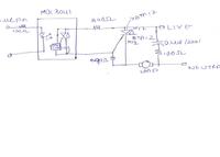
1 capacitor resistor in series should be bettween A1 A2 of Triac in the above cct it is wrong.
2 Make sure that 390R is Good
3 Make sure that 390R is bettween A1 and Gate

Now switch on the circuit without the input of opto connected to the micro cct. if it is ok then your circuit is ok
please check


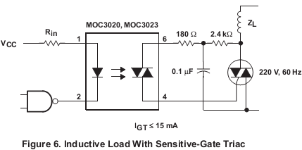
Actually I wanted to know why circuits are different for zero cross TRIAC driver and random phase TRIAC driver. It it really required to connect A2 and Gate with a resistor? If yes, why?

moc3041 contain inbuilt zero crossing detection circuit
when you are using these dont use zerocrossing detection using microcontroller

Thanks for the reply again.
I disconnected the supply of microcontroller section only and kept the supply ON to the Triac A.C load section. This time there was no switching ON-OFF of A.C loads on making movements of plug on extension socket as opposed to as earlier observaton. So, is it ok, or should i cut the track of input to opto-coupler from micro ckt.
Plz advice, if i have done the right testing as per your advice and as ther were no On-OFF of load on movement of A.C plug, whether the ckt is now full proof.
plz advice.