Continue to Site

Welcome to EDAboard.com

Welcome to our site! EDAboard.com is an international Electronics Discussion Forum focused on EDA software, circuits, schematics, books, theory, papers, asic, pld, 8051, DSP, Network, RF, Analog Design, PCB, Service Manuals... and a whole lot more! To participate you need to register. Registration is free. Click here to register now.

LM35 Temperature Sensor and 18f4520

Status
Not open for further replies.

starday

Junior Member level 1
Joined
Feb 8, 2013
Messages
15
Helped
0
Reputation
0
Reaction score
0
Trophy points
1,281
Activity points
1,385
Hi all,

Im new to C++ prog and i have a project which requires me using a 18f4520 with MPLAB IDE 8.80 and C18 compiler.

I have a LM35 which i will need to output the temperature value onto a 2x16 LCD.
Im using 18f4520 and making use of its ADC to do the conversion.

The problem now is that the LCD is not displaying anything. I had done a simple program displaying "Hello World" and it is OK so i assumed the hardware connections are fine.

I hope someone can enlighten me with this.

Below is my coding.

Code:
#include <p18f4520.h>
#include <delays.h>
#include <stdlib.h>

void Init_LCD(void);                // Initialize the LCD
void W_ctr_4bit(char);                // 4-bit Control word for LCD
void W_data_4bit(char);            // 4-bit Text Data for LCD
void Delay_1kcyc(void);            // 1000 cycles delay

#define LCD_DATA    PORTD
#define LCD_RW       PORTAbits.RA2       // RW signal for LCD
#define LCD_RS       PORTAbits.RA3       // RS signal for LCD
#define LCD_E         PORTAbits.RA1       // E signal for LCD

unsigned char     LCD_TEMP, i;
char Buffer[20];           // Buffer to hold temperature character string
unsigned int i;             // Index variable
unsigned int t;            // Variable for temperature

void main(void)
{
/* Declaration of variables */

    TRISA = 0b11110001;        // Set Pin RA0, RA4~RA7 as Input, RA1~RA3 as Output

    TRISB = 0b00000000;        // Set Port B as Output port (LEDs)
    PORTB = 0b00000000;        // Port B initialize as OFF (LEDs not lighted)

    TRISC = 0b00000000;        // Set PORT C as Output port (Buzzer)

    ADCON2 = 0b10000100;    // Result Right justified, Manual acquisition time, Fosc/4


/* Main program starts */

    Init_LCD();             // Init LCD 4-bit interface, multiple line

    while(1)
    {
        /* Measure Temperature */

        ADCON0 = 0b00000001;        // Select AN0 (channel 0) for Temp sensor, turn on ADC
        ADCON1 = 0b00001110;        // Select AN0 as ANALOG input, internal voltage
        Delay10TCYx(1);                // Acquisition time 10us (>=5us)

        ADCON0bits.GO = 1;            // Start A/D Conversion

        while(ADCON0bits.DONE);        // ADC completed?
        {
            t= (ADRES*500) / 255;     // ADRES (16bit) is the output of ADC, Convert to Degree Celsius in 8 bits format.
            W_ctr_4bit(0xC0)        // Move cursor to line 2 position 1
            itoa(t, Buffer);    // Convert number in variable t to a  string and store in variable Buffer
            i = 0;
            while (Buffer[i] != 0) W_data_4bit (Buffer[i++]);
        }
    }

}

/* LCD display initialization */
void Init_LCD()        
{            
    // Special Sequence a) to d) required for 4-bit interface

    Delay1KTCYx(15);            //   a) 15ms LCD power-up delay
    W_ctr_4bit(0x03);            //   b) Function Set (DB4-DB7: 8-bit interface)
    Delay1KTCYx(5);              //   c) 5ms delay
    W_ctr_4bit(0x02);            //   d) Function Set (DB4-DB7: 4-bit interface)
    W_ctr_4bit(0b00101000);        // Function Set - 4-bit, 2 lines, 5X7
    W_ctr_4bit(0b00001100);        // Display on, cursor off
    W_ctr_4bit(0b00000110);        // Entry mode - inc addr, no shift
    W_ctr_4bit(0b00000001);        // Clear display & home position
}
    
/* Write control word in term of 4-bit at a time to LCD */
void W_ctr_4bit (char x)
{
    LCD_RW    = 0;               // Logic ‘0’
    LCD_RS    = 0;                // Logic ‘0’
    LCD_TEMP     = x;           // Store control word
LCD_TEMP    >>= 4;            // send upper nibble of control word
LCD_E    = 1;                     // Logic ‘1’
LCD_DATA     = LCD_TEMP;
Delay1KTCYx(1);                // 1ms delay
LCD_E    = 0;                    // Logic ‘0’
Delay1KTCYx(1);                // 1ms delay
LCD_TEMP    = x;              // Store control word
LCD_TEMP    &= 0x0f;        // Send lower nibble of control word
LCD_E    = 1;                    // Logic ‘1’
LCD_DATA     = LCD_TEMP;
Delay1KTCYx(1);               // 1ms delay
LCD_E    = 0;                   // Logic 0’
Delay1KTCYx(1);              // 1ms delay
}

/* Write text data in term of 4-bit at a time to LCD */
void W_data_4bit (char x)
{
    LCD_RW     = 0;              // Logic ‘0’
    LCD_RS     = 1;               // Logic ‘1’
    LCD_TEMP     = x;           // Store text data
    LCD_TEMP  >>= 4;          // Send upper nibble of text data
    LCD_E     = 1;                // Logic ‘1’
    LCD_DATA = LCD_TEMP;
    Delay1KTCYx(1);             // 1ms delay
    LCD_E     = 0;                 // Logic ‘0’
    Delay1KTCYx(1);             // 1ms delay
    LCD_TEMP     = x;           // Store text data
    LCD_TEMP &= 0x0f;         // Send lower nibble of text data
    LCD_E     = 1;                // Logic ‘1’
    LCD_DATA = LCD_TEMP;
    Delay1KTCYx(1);            // 1ms delay
    LCD_E     = 0;                // Logic ‘0’
    Delay1KTCYx(1);            // 1ms delay
}

I need some verifications in this part to ensure that im on the right track.

Code:
while(1)
    {
        /* Measure Temperature */

        ADCON0 = 0b00000001;        // Select AN0 (channel 0) for Temp sensor, turn on ADC
        ADCON1 = 0b00001110;        // Select AN0 as ANALOG input, internal voltage
        Delay10TCYx(1);                // Acquisition time 10us (>=5us)

        ADCON0bits.GO = 1;            // Start A/D Conversion

        while(ADCON0bits.DONE);        // ADC completed?
        {
            t= (ADRES*500) / 255;     // ADRES (16bit) is the output of ADC, Convert to Degree Celsius in 8 bits format.
            W_ctr_4bit(0xC0)        // Move cursor to line 2 position 1
            itoa(t, Buffer);    // Convert number in variable t to a  string and store in variable Buffer
            i = 0;
            while (Buffer[i] != 0) W_data_4bit (Buffer[i++]);
        }
    }

Your help is much appreciated.
Thanks
 

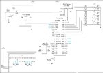
Attached is my schematic

Its an outdated one with a few pins reassigned as follows:

LCD module
RD0 >> DB4
RD1 >> DB5
RD2 >> DB6
RD3 >> DB7

Thanks, appreciated all help as im rushing before the deadline which is near and i have got to learn make a Web page out too..
untitled.JPG
 
Last edited:

you said you are using ADC conversion , but you didnt declare which adc channel to see from.
 

Yes i did declare actually..

I put it in this >>>

ADCON0 = 0b00000001; // Select AN0 (channel 0) for Temp sensor, turn on ADC

is there anything that i have missed out ?

Thanks.
 

That's not the way . You wait for 2 days , I will come up with a code for you regarding adc .
 

Alright thanks !!

But isnt that suppose to code as such format ?
Besides this, is there anything else in the code that is wrongly declared ?
 

Do you want display the temperature on the lcd ? If yes , you may need to declare something to look how many decimals place .
 

Hi InNeedOfHelp

Yes, i need to display out the temperature on the LCD.

How should i rewrite the codes then ?
Is my coding correct in the first place ?
 

Are you able to help me with the coding ?

I have no idea where have the coding gone wrong as im not well versed in C++ and unfortunately the deadline for me is nearing and i have got to design a web page for this as well..
So your help is very much appreciated !!
 

Are you able to help me with the coding ?

I have no idea where have the coding gone wrong as im not well versed in C++ and unfortunately the deadline for me is nearing and i have got to design a web page for this as well..
So your help is very much appreciated !!

Check this thread. there is a Hi Tech C Code. Change the ADCONx register values according to your project and PIC.
https://www.edaboard.com/threads/253183/
 

Hi Jayanth,

I will take a look and try with that.. But does my code really cant work or where is the prob with the coding ?

Thanks
 

Are you able to help me with the coding ?

I have no idea where have the coding gone wrong as im not well versed in C++ and unfortunately the deadline for me is nearing and i have got to design a web page for this as well..
So your help is very much appreciated !!

Sorry for the delay.

The attached file is a code which i used ADC conversion to display voltage readings. you may want to take a look at how i initialise the ADC part
 

Attachments

  • Voltage Test.rar
    57.1 KB · Views: 143

Thanks InNeedOfHelp.

I suppose you are using High Tech C compiler ?

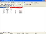
I have still some difficulties. From my Watch viewer, i am able to get the temperature and its ascii code using itoa().
Now my problem is how do i write correctly the coding to display out these ascii code to the LCD.
I seems to have hit a wall with the coding for displaying the data..
Something, somewhere is wrong but i cant pinpoint the problem.

Attached is my Watch window and coding..

Watch.JPG

Code:
#include <p18f4520.h>
#include <delays.h>
#include <stdlib.h>

void Init_LCD(void);		// Initialize the LCD
void W_ctr_4bit(char);		// 4-bit Control word for LCD
void W_data_4bit(char);		// 4-bit Text Data for LCD
void Delay_1kcyc(void);		// 1000 cycles delay

#define LCD_DATA	PORTD
#define LCD_RW   	PORTAbits.RA2   	// RW signal for LCD
#define LCD_RS   	PORTAbits.RA3   	// RS signal for LCD
#define LCD_E    	PORTAbits.RA1   	// E signal for LCD

unsigned char 	LCD_TEMP;
unsigned int i=0; 			// Index variable
unsigned int t=0; 			// Variable for temperature
unsigned int val;
char Buffer[5]; 			// Buffer to hold temperature character string

void main(void)
{
/* Declaration of variables */


	TRISA = 0b11110001;    	// Set Pin RA0, RA4~RA7 as Input, RA1~RA3 as Output

	TRISB = 0b00000000;    	// Set Port B as Output port (LEDs)
	PORTB = 0b00000000;	// Port B initialize as OFF (LEDs not lighted)

    //TRISC = 0b00000000;		// Set PORT C as Output port (Buzzer)

	/* Main program starts */

	Init_LCD(); 		// Init LCD 4-bit interface, multiple line

	while(1)
	{
		/* Measure Temperature */

		ADCON0 = 0b00000001;    	// Select AN0 (channel 0) for Temp sensor, turn on ADC
        		ADCON1 = 0b00001110;	// Select AN0 as ANALOG input, internal voltage
		ADCON2 = 0b00000100;    	// Result Left justified, Manual acquisition time, Fosc/4
        
		Delay10TCYx(1);        	// Acquisition time 10us (>=5us)

		ADCON0bits.GO = 1;        	// Start A/D Conversion

		while(ADCON0bits.DONE);    	// ADC completed?
		{
			val = ADRESH & 0xff;	// Taking only the values in ADRESH 
			t = ((val/255.0) * 500); 	// To get temperature in Degree Celsius, 255 = 2^8bits, 500 = 10mV/1deg
			
			if (t > 25)
			{
			PORTB = 0b10101010;
			}

			else
			{
			PORTB = 0b00000000;
			}

			W_ctr_4bit(0xC0);		// Move cursor to line 2 position 1

			itoa(t,Buffer);		// Convert number in variable t to a string and store in variable Buffer
			
			while (Buffer[i]!=0) 
			{
				W_data_4bit(Buffer[i++]);
			}
		}
	}

}


/* LCD display initialization */
void Init_LCD()		
{			
	// Special Sequence a) to d) required for 4-bit interface

	Delay1KTCYx(15);			//   a) 15ms LCD power-up delay
	W_ctr_4bit(0x03);			//   b) Function Set (DB4-DB7: 8-bit interface)
	Delay1KTCYx(5);			//   c) 5ms delay
	W_ctr_4bit(0x02);			//   d) Function Set (DB4-DB7: 4-bit interface)
	W_ctr_4bit(0b00101000);		// Function Set - 4-bit, 2 lines, 5X7
	W_ctr_4bit(0b00001100);		// Display on, cursor off
	W_ctr_4bit(0b00000110);		// Entry mode - inc addr, no shift
	W_ctr_4bit(0b00000001);		// Clear display & home position
}
	
/* Write control word in term of 4-bit at a time to LCD */
void W_ctr_4bit (char x)
{
	LCD_RW	= 0;			// Logic ‘0’
	LCD_RS	= 0;			// Logic ‘0’
	LCD_TEMP = x;			// Store control word
	LCD_TEMP >>= 4;			// send upper nibble of control word
	LCD_E = 1;			// Logic ‘1’
	LCD_DATA = LCD_TEMP;
	Delay1KTCYx(1);			// 1ms delay
	LCD_E = 0;			// Logic ‘0’
	Delay1KTCYx(1);			// 1ms delay
	LCD_TEMP = x;			// Store control word
	LCD_TEMP &= 0x0f;		// Send lower nibble of control word
	LCD_E = 1;			// Logic ‘1’
	LCD_DATA = LCD_TEMP;
	Delay1KTCYx(1);			// 1ms delay
	LCD_E = 0;			// Logic 0’
	Delay1KTCYx(1);			// 1ms delay
}

/* Write text data in term of 4-bit at a time to LCD */
void W_data_4bit (char x)
{
	LCD_RW = 0;			// Logic ‘0’
	LCD_RS = 1;			// Logic ‘1’
	LCD_TEMP = x;			// Store text data
	LCD_TEMP >>= 4;			// Send upper nibble of text data
	LCD_E = 1;			// Logic ‘1’
	LCD_DATA = LCD_TEMP;
	Delay1KTCYx(1);			// 1ms delay
	LCD_E = 0;			// Logic ‘0’
	Delay1KTCYx(1);			// 1ms delay
	LCD_TEMP = x;			// Store text data
	LCD_TEMP &= 0x0f;		// Send lower nibble of text data
	LCD_E = 1;			// Logic ‘1’
	LCD_DATA = LCD_TEMP;
	Delay1KTCYx(1);			// 1ms delay
	LCD_E = 0;			// Logic ‘0’
	Delay1KTCYx(1);			// 1ms delay
}
 

Hi starday,

I am not using Hi-Tech Compiler .
I am using the same software and same compiler with you .
Just that my sensor involves I2C routines and your's involves with ADC conversion.

For the display part , im not very sure .
Sorry . thats all i can helped you ..
 

Thanks mate for your help..

Lets see if someone else is able to help me with the doubt..
 

hello,

unsigned int val;
unsigned int t=0;

val = ADRESH & 0xff; // Taking only the values in ADRESH
t = ((val/255.0) * 500);

Why are you using only 8 bits for the ADC result ?
Resolution is very poor in this case , only 256 levels for 5000 mV
with a LM35DZ 10mV / ° C means scal is 500°C for 5V
so one step is 1.96°C !

if right justified you can use ADRESH <<8 + ADRESL to get 1024 points for 5000mV

You can also use C18 ADC library

Code:
#include <adc.h>

#ifndef Byte
#define Byte unsigned char
#endif

Byte CRam2[32];

void Init_ADC()
{
      //config lecture ADC 10 bits  voir page 297 DS
    ADCON0bits.ADON=1;      // ADC enabled chanel 0
    ADCON1bits.PVCFG=0;   // +Vref = +5V AVdd
    ADCON1bits.NVCFG=0;   // -Vref = Gnd AVss 
    ADCON2bits.ADFM=1;     // right justified
    ADCON2bits.ACQT2=1;
    ADCON2bits.ACQT1=1;
    ADCON2bits.ACQT0=0;    // 16 TAD
    ADCON2bits.ADCS2=1;
    ADCON2bits.ADCS1=0;
    ADCON2bits.ADCS0=1;    // Fosc/16
  }

 unsigned char *fltToa (float x, unsigned char *str,char precision)
{
/* converts a floating point number to an ascii string */
/* x is stored into str, which should be at least 30 chars long */
unsigned char *adpt;
int ie, i, k, ndig;
double y;
adpt=str;
ndig = ( precision<=0) ? 7 : (precision > 22 ? 23 : precision+1);
ie = 0;
/* if x negative, write minus and reverse */
if ( x < 0)
  {
  *str++ = '-';
  x = -x;
  }
/* put x in range 1 <= x < 10 */
if (x > 0.0) while (x < 1.0)
  {
  x *= 10.0;		// a la place de =*
  ie--;
  }
while (x >= 10.0)
  {
  x = x/10.0;
  ie++;
 }

// in f format, number of digits is related to size 
 ndig += ie;				// a la place de =+
//round. x is between 1 and 10 and ndig will be printed to
// right of decimal point so rounding is ... 
for (y = i = 1; i < ndig; i++)
  y = y/10.;
x += y/2.;					
if (x >= 10.0) {x = 1.0; ie++;} 
if (ie<0)
  {
   *str++ = '0'; *str++ = '.';
   if (ndig < 0) ie = ie-ndig;
   for (i = -1; i > ie; i--)  *str++ = '0';
  }
for (i=0; i < ndig; i++)
  {
  k = x;
  *str++ = k + '0';
  if (i ==  ie ) *str++ = '.';
  x -= (y=k);	
  x *= 10.0;	
  }
*str = '\0';
return (adpt);
}


unsigned int  Mesure_ADC(int canal)
{ unsigned int EA;
  ADCON0=1 + (canal<<2);   // ADON=1 et choix de canal 
  Delay10TCYx( 10 ); // Delay for 100TCY
  ConvertADC(); // Start conversion
  while( BusyADC() );
  EA = ReadADC(); // Read result
  return (EA);
}  

void main()
{
 .. etc .....

   InitADC();   // [B]<-- to adapt to the proper PIC18F4520[/B]

 //T° Ext LM35DZ 0mV at 0°C
   EAx=Mesure_ADC(1);
  f2=(float)EAx*0.48828125;   //  0.488=500.0/1024.0 
   k=fprintf(_H_USART,"Temperature:%4d  %s°C ; ",EAx,fltToa(f2,CRam1,2));

...
} // main

replace H_USART by your LCD function
 

Hi paulfjujo

i am using the 4-bit setup for the LCD so i cant use the full 10bits of ADC.

My setup is such that after i have the input from sensor, i will have a LCD function to process 4 bits by 4 bits and display it.
From my Watch window, i can see the correct display but it just cannot display out on LCD.
 

hello
i am using the 4-bit setup for the LCD so i cant use the full 10bits of ADC.

There is no relation chip beetwen using 4bits LCD and showing 10bits from ADC !
LCD in 4 bits mode can show 8 bits data
you can display 10 bits data on LCD ! or more ..


to display the value from ADC ( binary value), you have to convert it in BCD mode
and add '0' or 48 to each digit before to send to the LCD.

ex: 769 ADC value will give 301h (binary format) to convert to 769 (in bcd format)
7+48=55 -> 1rst digit gives '7' in ascii format
0+48=48 -> '0' second digit in ascii
1+48 =49-> '1' third digit in ascii
you must send Byte to LCD not 4bits only!
so you need to send 2 times 4bits to send a byte.
MSB of byte , then LSB of the byte
see details in void XLCDPut(char data)

use XLCD from C18 library ,
adapt your pinouts with the file XLCD.DEF or directly like in this below example

Code:
/*
 * rev PF Dec 2011
 Definition de l'afficheur en DUR !! donc non parametrable par fichier DEF
 Hardware lié:
 PORTB pour DATA & CTRL
 PORTB Upper B4..B7 pour LCD Data D4..D7   avec D0..D3 relies au Gnd (0V)
 PORTB B2 pour RS LCD    B3 pour pin EN LCD
 B0 et B1 sont dispo!
 */


/* DATA_PORT defines the port to which the LCD data lines are connected */

#define XLCD_DATAPORT       PORTB
#define XLCD_DATAPORT_TRIS  TRISB

//CTRL_PORT defines the port where the control lines are connected.

//ReadWrite Pin
#define XLCD_RWPIN       PORTBbits.RB1
#define XLCD_RWPIN_TRIS  TRISBbits.TRISB1

//RS Pin
#define XLCD_RSPIN   PORTBbits.RB2
#define XLCD_RSPIN_TRIS  TRISBbits.TRISB2

//Enable Pin
#define XLCD_ENPIN   PORTBbits.RB3
#define XLCD_ENPIN_TRIS  TRISBbits.TRISB3

void XLCDInit(void);                                //to initialise the LCD
void XLCDPut(char data);                            //to put dtat to be displayed
void XLCDPutRamString(char *string);                //to display data string in RAM
void XLCDPutRomString(rom char *string);            //to display data stringin ROM
//char XLCDIsBusy(void);                              //to check Busy flag
void XLCDCommand(unsigned char cmd);                //to send commands to LCD           
//unsigned char XLCDGetAddr(void);
//char XLCDGet(void);

void Pulse_E (void);
void XLCD_pos(char L,char posX);
void Erase_Ligne(char L1);
 

#define XLCDL1home()    XLCDCommand(0x80)
#define XLCDL2home()    XLCDCommand(0xC0)
#define XLCDClear()     XLCDCommand(0x01)
#define XLCDReturnHome() XLCDCommand(0x02)

void XLCDDelay15ms(void);
void XLCDDelay4ms(void);
void XLCDDelay100us(void);
void XLCD_Delay500ns(void);
void XLCDDelay(void);


/*********************************************************************
 * Function      : void XLCDInit(void)
 * PreCondition  : None
 * Input         : None
 * Output        : None
 * Side Effects  : None
 * Overview      : LCD is intialized
 * Note          : This function will work with Hitachi HD447780 LCD controller.
 ********************************************************************/

void XLCDInit(void)
{

//PORT initialization  
//4bit mode
//Upper 4-bits of the DATAPORT output
XLCD_DATAPORT_TRIS  &= 0x0f;
XLCD_DATAPORT &= 0x0f;
//control port initialization
XLCD_RSPIN_TRIS =0;                         //make control ports output
XLCD_ENPIN_TRIS =0;
XLCD_RSPIN  =0;                             //clear control ports
XLCD_ENPIN  =0;

//initialization by instruction
//  envoi 3 fois de suite 0x03H sur le quarter MSB du PORTB
XLCDDelay15ms(); 
// Upper nibble interface
XLCD_DATAPORT   &= 0x0f;        // 1ere init
XLCD_DATAPORT   |= 0b00110000;
Pulse_E() ;
XLCDDelay4ms();

// Upper nibble interface
XLCD_DATAPORT   &= 0x0f;        // 2em ini
XLCD_DATAPORT   |= 0b00110000;
Pulse_E() ;
XLCDDelay4ms(); 
   
// Upper nibble interface
XLCD_DATAPORT   &= 0x0f;        // 3em init
XLCD_DATAPORT   |= 0b00110000;
Pulse_E() ;
XLCDDelay4ms();    
    
//Force le mode 4 Bits    0x02H sur quartet MSB du PortB  
//Function SET Commande 0 0 1 DL N F X X  avec RS=0 RW=0
// Upper nibble interface
XLCD_DATAPORT   &= 0x0f;        // Clear upper port
XLCD_DATAPORT   |= 0b00100000;
Pulse_E() ;
   
//Function SET Commande 0 0 1 DL N F X X  avec RS=0 RW=0
//Definit la taille de l'interface (DL=0 pour mode 4 bits, DL=1 pour mode 8 bits),
// le nombre de lignes (NL=0 pour 1 ligne, N=1 pour 2 ou 4 lignes),
// et la taille des fontes (F=0 pour des cars 5x7, F=1 pour des cars 5x10). 
XLCDCommand(0b00101000);    // 0x28     2Line 5x8

//Display on/off control  0 0 0 0 1 D C B 
// affichage (D), curseur (C), clignotement du curseur (B).
XLCDCommand(0b00001000);    //display off
XLCDCommand(0b00000001);    //display clear

//Entry mode setting
//Entry mode command " 0 0 0 0 0 1 ID S "
//ID =0 no cursor increment during read and write
//ID =1 cursor increment during read and write
//S =0 no display during read and write
//S =1 display shift 
       
 XLCDCommand(0b00000110);    //if cursor inc and no display shift

//Display on off ,Blink ,cursor command set 
//"0 0 0 0 1 D C B "
//D=1 dislay on, C=1 cursor on, B=1 blink on
XLCDCommand(0b00001111);    //display on cursor on blink on
 
// end of initialization
  return;
}

 
void  Pulse_E (void)
{
XLCD_ENPIN = 1;         
XLCD_Delay500ns();   
XLCD_ENPIN = 0;  
 }
  
 
/**********************************************************
 * Function         : void XLCDCommand(unsigned char cmd)
 * PreCondition     : None
 * Input            : cmd - Command to be set to LCD.
 * Output           : None
 *********************************************************/
void XLCDCommand(unsigned char cmd)
{
XLCDDelay();
XLCD_RSPIN=0;
XLCD_ENPIN=0;
XLCD_DATAPORT &=0x0f;               //clear port
XLCD_DATAPORT |= cmd&0xf0;          //write upper nibble of cmd to UPPERT port
Pulse_E();      
XLCD_DATAPORT &= 0x0f;              //clear port and shift left 4 times
XLCD_DATAPORT |= (cmd<<4)&0xf0;	    //write lower nibble of cmd  to UPPERT port
Pulse_E ();
return;
}
/******************************************************
 * Function         :XLCDPut()
 * PreCondition     :None
 * Input            :data - donnee a transmettre au LCD.
 * Output           :None
 *****************************************************/
void XLCDPut(char data)
{
XLCDDelay();
XLCD_RSPIN=1;
XLCD_ENPIN=0;
XLCD_DATAPORT &=0x0f;               //clear port
XLCD_DATAPORT |= data&0xf0;         //write upper nibble to port
XLCD_ENPIN = 1;                     // Clock the cmd in
XLCD_Delay500ns();
XLCD_ENPIN = 0;
        
XLCD_DATAPORT &= 0x0f;              //clear port
XLCD_DATAPORT |= (data<<4)&0xf0;	//shift left 4 times
XLCD_ENPIN = 1;
XLCD_Delay500ns();
XLCD_ENPIN = 0;
return;
}


/***************************************************
 * Function         :XLCDPutRomString(rom char *string)
 * PreCondition     :None    
 * Input            :None
 * Output           :Displays string in Program memory
 * Note             :is lways blocking till the string is written fully
 *****************************************************/

void XLCDPutRomString(rom char *string)
{
     while(*string)                         // Write data to LCD up to null
    {    
        XLCDPut(*string);                   // Write character to LCD
        string++;                           // Increment buffer
    }
    return;
}
/****************************************************
 * Function         :XLCDPutRomString(ram char *string)
 * PreCondition     :None    
 * Input            :None
 * Output           :Displays string in Ram memory
 * Note             :is lways blocking till the string is written fully
 ******************************************************/
void XLCDPutRamString(char *string)
{
    while(*string)                          // Write data to LCD up to null
    {       
        XLCDPut(*string);                   // Write character to LCD
        string++;                           // Increment buffer
    }
    return;
}

void XLCD_pos(char L,char posX)
{
 char x;
 if (L==1) x=0x80+posX;
 if (L==2) x=0xC0+posX;
 XLCDCommand(x);   
} 

void Erase_Ligne(char L1)
{
 char x;
 XLCD_pos(L1,0); //  retour en debut de ligne
 for (x=0;x<16;x++) XLCDPut(' ');
 XLCD_pos(L1,0); 
}

void XLCDDelay15ms (void)
{
    int i;
    for(i=0;i<10000;i++)
    {
    Nop();
    }
    return;
}

void XLCDDelay4ms(void)
{
    int i;
    for(i=0;i<2500;i++)
    {
    Nop();
    }
    return;
}

void XLCD_Delay500ns(void)
{
    Nop();
    Nop();
    Nop();
}

void XLCDDelay(void)
    {
    int i;
    for(i=0;i<1000;i++)
        {
        Nop();
        }
    return;
    }
 

Status
Not open for further replies.

Similar threads

Part and Inventory Search

Welcome to EDABoard.com

Sponsor

Back
Top