Continue to Site

Welcome to EDAboard.com

Welcome to our site! EDAboard.com is an international Electronics Discussion Forum focused on EDA software, circuits, schematics, books, theory, papers, asic, pld, 8051, DSP, Network, RF, Analog Design, PCB, Service Manuals... and a whole lot more! To participate you need to register. Registration is free. Click here to register now.

buck boost converter hardware problem

Status
Not open for further replies.

azarutz

Member level 2
Member level 2
Joined
Mar 4, 2012
Messages
42
Helped
1
Reputation
2
Reaction score
1
Trophy points
1,288
Location
India
Activity points
1,579
Hi i designed a buck boost converter (inverted topology) to charge 4, 12v lead acid battery each capacity is 100 Ah .
buck boost circuit spec is 20 to 70 V input and 54 V output .
Untitled.png
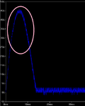
i have to limit the starting current of the inductor actually i designed it for max 15A but it goes to 42A at starting .it showed in pic with circled in rose color.
Untitled1.png
1) is there any way to limit the starting current to inductor without affecting normal operation ?
2) voltage across capacitor is taken to battery. is it work in that way?

thanks in advance .
 

Re: 1) You could use an inrush current limiter to limit the current at start up. This device (usually a thermistor) has a significantly higher resistance when cold (20 deg C) than when it reaches it's operational temperature (tens of miliohms at 70deg C).
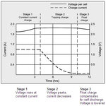
Re: 2) To properly charge Lead acid battery you need to vary voltage and current depending on the state of charge of the battery. You need stand-by (or float) charging, constant voltage charging and constant current charging.
See the attached diagram for a typical charging cycle of a single lead acid cell

clead1.jpg
 
1.

Try a lower value for your smoothing capacitor. It is like a short circuit when it has no charge on it. That is why you see a high current surge during startup, more so with a high Farad value.

2.

Is your 45V source able to provide 42A? It has a certain amount of internal resistance, does it not?
 
Hi i designed a buck boost converter (inverted topology) to charge 4, 12v lead acid battery each capacity is 100 Ah .
buck boost circuit spec is 20 to 70 V input and 54 V output .
View attachment 86585

One other thing I just noticed is that your battery (and C1) are connected the wrong way round

- - - Updated - - -

1.

Try a lower value for your smoothing capacitor. It is like a short circuit when it has no charge on it. That is why you see a high current surge during startup, more so with a high Farad value.

The C1 is getting charged from the inductor in the off state. It is the inductor that is responsible for this high current.

2.

Is your 45V source able to provide 42A? It has a certain amount of internal resistance, does it not?

Even if this is true, this (or possibly any) circuit should not be designed to operate only with sources not capable of providing more than certain amount of current...
 

Re: 1) You could use an inrush current limiter to limit the current at start up. This device (usually a thermistor) has a significantly higher resistance when cold (20 deg C) than when it reaches it's operational temperature (tens of miliohms at 70deg C).
Re: 2) To properly charge Lead acid battery you need to vary voltage and current depending on the state of charge of the battery. You need stand-by (or float) charging, constant voltage charging and constant current charging.
See the attached diagram for a typical charging cycle of a single lead acid cell

View attachment 86588

Hi thanks for reply is there any way to include series resistance at starting and exclude it after some time . is thermistor do that job by reducing its resistance after some time?

- - - Updated - - -

1.

Try a lower value for your smoothing capacitor. It is like a short circuit when it has no charge on it. That is why you see a high current surge during startup, more so with a high Farad value.

2.

Is your 45V source able to provide 42A? It has a certain amount of internal resistance, does it not?


Hi thanks for reply actually i designing for battery from wind turbine is rated for 1.8kw @ 6m/s . i usually get 20 to 70V dc after rectification and 10 to 15 A depends on wind speed. surely it will not give 42A . i tested it with a RPS (Regulated Power Supply) rated with 110V,5A DC . At starting i gave 3V to buck boost converter and it takes 2A and after i rise it to 10V then rps trips .so that we planning to include a resistance in series with inductor .
after that we connected ammeter in series with capacitor no current flow throw it.
 

The C1 is getting charged from the inductor in the off state. It is the inductor that is responsible for this high current.

Yes, I forgot how the inductor also contributes to this effect on startup.

However if the battery is already connected, then it previously charged the capacitor to 48V. The capacitor does not gobble current and there is no startup surge. (Which allows us to conclude that the problem mentioned in the OP will not be so bad after all.)

But if it were an ordinary load...
The uncharged capacitor admits a current surge only during switch-Off.
The coil tries to continue the current surge during both switch-On and switch-Off.
In so doing, it boosts the charge level on the capacitor.
This continues for several cycles before the load voltage subsides to normal operating level.

One other thing I just noticed is that your battery (and C1) are connected the wrong way round

The buck-boost inverts the supply polarity.

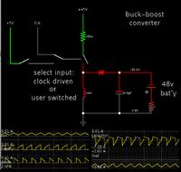
Screenshot of my simulation:


A current mode controller for the converter solves the problem.
 

A current mode controller for the converter solves the problem.

Hi, Can you tell me what current mode controller is and how i can use this?.
Thanks in advance
 

A current mode controller doesn't set a constant PWM duty cycle but ends the on period when a certain peak current is reached.

Many industry standard switched mode voltage regulator ICs are using this control method, particularly for flyback and boost topology.
 
Hi,my 330uF electrolytic capacitor oil leaks from its bottom and capacitor come out of its plastic sheet over it. while working with 14V input , 50% duty cycle and 2.7A input current .
i connected capacitor in correct polarity. i don't why that happened .
 

Hi to recharge the battery can i connect directly across the capacitor or add any resistor in parallel with capacitor then i connect battery across it ?
 

Hi,my 330uF electrolytic capacitor oil leaks from its bottom and capacitor come out of its plastic sheet over it. while working with 14V input , 50% duty cycle and 2.7A input current .
i connected capacitor in correct polarity. i don't why that happened .

My simulation shows that the capacitor has several amps going back and forth through it, continually. I would not be surprised if it overheated.

Remember that the capacitor may also be exposed to a large current surge on power-up. However this by itself would not be likely to ruin a capacitor.

Question: Did you operate the converter without the battery being connected? If so the capacitor charge could have risen to a very high voltage, in the hundreds of volts. The result would be a ruined capacitor. (Unless your control circuitry has safeguards against overvoltage.)
 

Question: Did you operate the converter without the battery being connected? If so the capacitor charge could have risen to a very high voltage, in the hundreds of volts. The result would be a ruined capacitor. (Unless your control circuitry has safeguards against overvoltage.)

yes sir, instead i connected 50 ohm , 10A rheostat across the capacitor . In hardware after i replacing diode input current reduced , before there was short circuit through inductor . I get 3A for 15V input .
Is there any way to prevent overheating of capacitor?
 

Hi,till now i encountered two problem in converter
1) my buck boost converter didn't boost voltage in hardware with increment of duty cycle . In output it shows only input voltage value what ever i gives.
2) I connected two 680uF capacitor in parallel to get 1.36mF . when i increase input voltage around 25V one capacitor exploded .
I don't know what is the problem if somebody know help me.
 

Hi,till now i encountered two problem in converter
1) my buck boost converter didn't boost voltage in hardware with increment of duty cycle . In output it shows only input voltage value what ever i gives.

This suggests the converter is not oscillating. Perhaps the switching device is continually off? Then the supply voltage goes straight to the output unhindered.

2) I connected two 680uF capacitor in parallel to get 1.36mF . when i increase input voltage around 25V one capacitor exploded .
I don't know what is the problem if somebody know help me.

The most likely cause of a capacitor exploding is that it was exposed to a volt level which is greater than its rating.

You are building a converter which is intended to carry more than a kW of power. I myself would hesitate to construct such a project. For one thing I would be concerned about a battery explosion (although capacitor explosions are not much better).

You are combining heavy current and potentially high voltage. All components must be rated to withstand any anticipated condition. The output volt level can soar sky-high if you disconnect the load in a moment of absent-mindedness.

As for the capacitor value, it is wise to connect several capacitors in parallel. This is needed to divide the current load which amounts to several amperes. (I'm re-stating my post #13 here.)

However I'm afraid to suggest anything under the circumstances except a comparatively safe recommendation that you leave a sufficient load connected all the time, in order to prevent output volt levels from rising above 60 V or so. If voltage is sufficiently high it can generate a spark, and if the spark happens inside a battery it can explode, causing possible injury and acid spillage.

------------------------------

In case it will help to experiment with an interactive animated simulator, here is a link.
Click it and it will open the falstad.com/circuit website, load my schematic, and run it on your computer.

https://tinyurl.com/adg4dx3

I altered some values.

You can change values by right-clicking a component and selecting Edit.
 
Status
Not open for further replies.

Similar threads

Part and Inventory Search

Welcome to EDABoard.com

Sponsor

Back
Top