Continue to Site

Welcome to EDAboard.com

Welcome to our site! EDAboard.com is an international Electronics Discussion Forum focused on EDA software, circuits, schematics, books, theory, papers, asic, pld, 8051, DSP, Network, RF, Analog Design, PCB, Service Manuals... and a whole lot more! To participate you need to register. Registration is free. Click here to register now.

microwave power detector design at 11 GHz

Status
Not open for further replies.

per_lube

Advanced Member level 4
Full Member level 1
Joined
Sep 29, 2010
Messages
107
Helped
17
Reputation
34
Reaction score
17
Trophy points
1,298
Activity points
2,120
Hi,

I have to build a microwave power detector works at 11 GHz for a point to point communication application.

Could anyone shed some light on a good tutorial or some instructions on building a microwave power detector with Schottky barrier diodes at 11 GHz?

I found some datasheets and app. notes from Skyworks & Avago. They explain the theory well.
However they does not provide necessary information on practical implementation which makes difficult to understand the design steps for a novice like me

I got some specific problems:

1. Does the circuit requires an impedance matching circuit between input RF Port and diode?
2. What is the value for DC blocking capacitor for the RF input port at 11 GHz?
3. What is the best value for smoothing capacitor at the DC output side of the power detector for this freq. & how to determine it?

cheers,
per_lube
 

There are now many useful MMICs mass produced for the mobile phone infrastructure that you would find useful.

Log-amp and other detectors made for everything from closed-loop transmitter control to spectrum analyser instrumentation, including types that are blind to modulation, and some have very wide dynamic range and an output proportional to dB.

While there several manufacturers that make RF detectors, and I have no vested interest in any, I have used detectors from Analog Devices, and I am aware of others from Linear Technology (linear.com). Your 11GHz requirement is a tough call. The AD8319 gets to 10GHz, and might be persuaded to 11GHz. You don't say if all the 11Ghz signal is available to offer at the detector, or if you have to sample it with a (say) -30dB coupler. Also, what the available level is. These things strongly affect the design choices.

The sure way to do it is to use a down-converter IC (same website), and get the signal within the range of something like AD8363 (6GHz linear ) or AD8362 (3.8GHz 65dB range) Take your time to pick through the choices, and read the Application Notes, especially those on transmitter control. The detector circuits can be lifted.

Using these MMICs is LOTS easier than going from scratch with diodes, even if you have to throw in a down-convert with oscillator. The hard stuff is done in the RFIC. Getting the signal onto microstrip, a sample into the chip, and maybe get it off again into a connector is awkward at anything above 6Ghz, but OK with care. Choosing an IF frequency at (say) around 500 to 800Mhz still uses the same detector, but your signal routing life becomes way easier.

At 11GHz, a 1pF or 2pF capacitor will do. Maybe a capacitor made of coupled trace in microstrip or coplanar WG. There will be discontinuity radiation from a SMT capacitor, but it may not matter much. 0402 size maximum.

You don't put smoothing capacitors across a op-amp output, but use the provided noise filter pins instead. If you used a (tiny) diode set, maybe a 2-stage smoother with 20pF first.
 
Last edited:
Thanks Darktrax for your detailed explanation.

For this power detector, I should use the minimum number of components to make it very cheap and using a ready-made chip is not possible.
However, the sensitivity will not be an issue since a short range communication is used.

Just one more question,

Could you please explain whether we need to consider the operating frequency of passive components such as caps, resistors and inductors?

If I get any cap or inductor with 0402 package, will it work without a problem at this frequency (11 GHz) ? or is there special range of passive components for Microwave frequencies?

cheers,
per_lube
 

There is so much about "simple" diode detectors that make them somewhat un-simple.
They are square law devices that "change" at some power level from true log law proportional to dB to something else still non-linear.
There is a notorious temperature dependence that needs clever circuits involving another diode to cancel.
They have a forward voltage offset that somewhat modifies what they do for levels below 300mV.
Use Google and read up on detector circuits - there's lots!

At 11 GHz, if you have to have powers available high enough that you can take a coupled sample straight into a series diode feeding a capacitor, you run into a whole mess of other problems. A 2-diode trick is better.

Very important is the levels you want to measure. A 2-diode detector using zero-bias Schottky (Avago I think) feeding a chopper sampler (very cheap!) can let you read down to about -60dBm. BUT... you have quite a bit of circuit to build.
Though it worked with a microwave diode pair in one package, + 2 DIP ICs, I don't want to do this again. detector.jpeg

My last detector was a 1-component thing in a small outline 8-pin SMD that cost about £7 ($11). It would work to 2.7GHz. There were some more minor bits to deliver the regulated supply voltage, and 1 op-amp (approx $2) plus some resistors to get the DC output to a level we could send to a data-logger. It was a fast, low cost solution.

- - - Updated - - -

Here is an Agilent temperature compensated design using diode packs you can get from Avago (or maybe their modern equivalent). It looks (only just!) good enough for 11GHz, but putting it on low-loss circuit board for a single build is hardly cheap!

detector1.jpeg

Hope this helps..
 
  • Like
Reactions: per_lube

    V

    Points: 2
    Helpful Answer Positive Rating

    per_lube

    Points: 2
    Helpful Answer Positive Rating
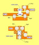
I made this power detector and it works well... :smile:

It detects power levels up to -30 dBm. is that the typical value? or can it be improved more?

I applied up to 15 dBm input power and works well up to that power input as well...

Thanks for your help...

cheers,
per_lube
 

Status
Not open for further replies.

Part and Inventory Search

Welcome to EDABoard.com

Sponsor

Back
Top