Continue to Site

Welcome to EDAboard.com

Welcome to our site! EDAboard.com is an international Electronics Discussion Forum focused on EDA software, circuits, schematics, books, theory, papers, asic, pld, 8051, DSP, Network, RF, Analog Design, PCB, Service Manuals... and a whole lot more! To participate you need to register. Registration is free. Click here to register now.

Data unsynchronization

Status
Not open for further replies.

syedshan

Advanced Member level 1
Joined
Feb 27, 2012
Messages
463
Helped
27
Reputation
54
Reaction score
26
Trophy points
1,308
Location
Jeonju, South Korea
Visit site
Activity points
5,134
Hi all,

We are designing a scanning system using FPGA and currently we have unsynchronization problem and I want if someone has experience about it to please give comments over it.
Our system works as trigger is given to the FGPA, it starts to fetch data from ADC (which is continually giving out data). Hence only data after trigger is of any worth and is stored
in the FIFO.
The trigger is 500 Hz but as shown in figure that after each trigger the data is shifted and hence actually corrupted since we need the data as first figure each time.
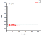
r.PNG

now this figure is data after 52nd signal
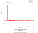
r2.PNG

and the following data is after 200 signals. Every one can clearly see that the trigger and signal are shifted wayyy forward because of which data corruption occurs.
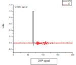
r3.PNG

After each trigger the wave form from ADC is stored in FIFO which I read and save into the file using c++.
One thing that I understand is may be file saving is taking lot of time and hence before next trigger comes the system is not free...

Does any one has any idea or suggestion
 

Well you have 2ms to read the data do you know if your C++ program or the HW can read it that fast?
 

You should be able to determine if your fifo is overflowing, if it is then you are not writing data fast enough to the file. (That doesn't look like the case to me).

I'm not sure what your graphs are showing; it looks like the trigger and data are shifted in time, but the data relative to the trigger looks proper . Why do you think there's a problem? What is the "t0" on your x-axis? Please explain more what we are looking at.
 

Thank you for your responses.

Well you have 2ms to read the data do you know if your C++ program or the HW can read it that fast?
Well one thing is sure that because of reading this I am having timing misalignment, as the frequency of trigger event increase, the misalignment increases drastically.


Barry,
yes it is like this, but the trigger is actually at the time '0' at each event, actually the signal is captured after the trigger (hence t=0). and we need all 200us 's data for processing
moreover this scanning is only 5 Hz (mistakenly I write 500Hz in previous post) but my actual triggering frequency is 1KHz or 500Hz Hence with fast trigger the shifting is quite greater than
what I showed, i.e. after each signal I get the marginal shift. Ultimately signal loss occurs.
For this reason I think that I have FIFO full state. How to check this since I am using the PCIe based FPGA card which does not have JTAG for analyzing using Logic Analyzer.


Hope you understand,
Thank you
Shan
 
Last edited:

You should be able to determine if your fifo is overflowing, if it is then you are not writing data fast enough to the file. (That doesn't look like the case to me).
Don't you mean reading data fast enough? That would result in overflows. Not writing fast enough into the FIFO would result in underflow.

I'm not sure what your graphs are showing; it looks like the trigger and data are shifted in time, but the data relative to the trigger looks proper . Why do you think there's a problem? What is the "t0" on your x-axis? Please explain more what we are looking at.
syedshan will have to clarify, but based on the poorly described operation it would seem that they trigger the ADC capture of a block of data. If this data is always the same size block, which I think is the case based on the way the OP expects the data to show up. I think he's either reading stale data or overflowing the FIFO causing discontinuities in the data.

Do you monitor the FIFO depth or Flags from the SW? You need to do that if you want to reliably read the data from the FIFO without over/under flow.

I would probably avoid a FIFO in this type of design and use a ping pong buffer. The capture data will always be loaded starting at address 0 so there is no ambiguity in the data alignment. Either that or at least include a side-band in the FIFO that flags the start of a new block of capture data. At least in that way the SW will know if it has over/under flow of data samples.

- - - Updated - - -

Well one thing is sure that because of reading this I am having timing misalignment, as the frequency of trigger event increase, the misalignment increases drastically.

Barry,
yes it is like this, but the trigger is actually at the time '0' at each event, actually the signal is captured after the trigger (hence t=0). and we need all 200us 's data for processing
moreover this scanning is only 5 Hz (mistakenly I write 500Hz in previous post) but my actual triggering frequency is 1KHz or 500Hz Hence with fast trigger the shifting is quite greater than
what I showed, i.e. after each signal I get the marginal shift. Ultimately signal loss occurs.
For this reason I think that I have FIFO full state. How to check this since I am using the PCIe based FPGA card which does not have JTAG for analyzing using Logic Analyzer.
This confirms what I just posted.

So change to reading from a ping pong buffer so you can't read misaligned data, you will likely still overflow but the data will be properly aligned just overwritten. If you're doing any averaging on the data captured this probably won't result in any problems.

If you can't allow overwriting data then you'll need to add some PCIe DMA capability to the FPGA design so you can get data out of the FPGA at a faster rate. I'm assuming you're probably reading the data with individual PCIe read cycles, which will be very inefficient.

- - - Updated - - -

Hey this might get you started on DMA for your PCIe core...

https://www.fpgarelated.com/usenet/fpga/show/42591-1.php
 
Don't you mean reading data fast enough? That would result in overflows. Not writing fast enough into the FIFO would result in underflow.

Writing to the file implies READING from the fifo.

Regardless, I'm still confused. Shan, what do you mean you are 'scanning' at 5Hz but 'triggering' at 1KHz? Do you mean sampling? I think you've got everybody confused here.
 

Writing to the file implies READING from the fifo.
Sorry I read fifo instead of file. I guess I'm getting in the habit of reading what I think posters are trying to say than what is really written ;-)

Regardless, I'm still confused. Shan, what do you mean you are 'scanning' at 5Hz but 'triggering' at 1KHz? Do you mean sampling? I think you've got everybody confused here.
I'm confused too. You really need use consistent terminology and define what that terminology means in the context of your post.

You initially started discussing the trigger is 500Hz but now are stating the scanning is 5Hz, which you mistakenly wrote as 500Hz. Which is it a trigger or scanning? Also what do those terms mean in the context of your second post?

Are you trying to tell us the sampling triggers occur at 500Hz or 1kHz intervals and the scanning (i.e. reading the FIFO) by the host SW is done at 5Hz intervals?

Regardless of the terminology. I think that if you are reading a FIFO and writing the results to a file your system won't be fast enough unless the amount of data is very small and/or the intervals between captures is increased significantly. As we know little about how your SW works I can only assume it's not using DMA or a driver that directly accesses the host's disk drive routines. That would be the highest performing method of capturing data. You could improve that even more by adding a SSD to your system for the data capture.
 
Last edited:

Hello both,

Thank you very much for putting in effort and giving your time for my problem. and sorry for me not being clear much.

moreover this scanning is only 5 Hz (mistakenly I write 500Hz in previous post) but my actual triggering frequency is 1KHz or 500Hz Hence with fast trigger the shifting is quite greater than

What I actually meant was, that our actual system scanning and hence triggering speed is 500Hz or 1Khz, but for testing purpose I drop down scanning speed to to 5Hz just to verify that is it really
the problem of writing into the file in PC that consumes time. (and I still think with 5Hz it is same although the result is far better than 1KHz).

Are you trying to tell us the sampling triggers occur at 500Hz or 1kHz intervals and the scanning (i.e. reading the FIFO) by the host SW is done at 5Hz intervals?
Your confusion was completely correct since I think I phrased it wrong and messed it up. Hope now it is clear that by scanning and triggering speed I mean the same, just for test case I scan at 5Hz, later we have to do at 1KHz.
We are actually scanning the area using Laser with triggering frequency. This scanning is same as raster scanning actually. Then Ultrasonic sensor(PZT sensor) will sense the energy caused by laser impinging, which ultimately will generate a movie for X*Y area scanning.
Hence we cannot afford to lose data points at even each impinging point. Each impinging interval(trigger or scan interval) is (for testing only) 1KHz in actual system, which is veeery veeery fast I think.

Regardless of the terminology. I think that if you are reading a FIFO and writing the results to a file your system won't be fast enough unless the amount of data is very small and/or the intervals between captures is increased significantly. As we know little about how your SW works I can only assume it's not using DMA or a driver that directly accesses the host's disk drive routines. That would be the highest performing method of capturing data. You could improve that even more by adding a SSD to your system for the data capture.

Our software reads in data through PCIe using DMA (PCIe speed for virtex 5 based board (as the manufacturer said) is 100MHz as they designed in Xilinx core generator).

ads_ee, thank you for your idea of ping-pong buffer I have started looking into it and am surely going to look if it works for fast scanning speed.

Thank you both again for putting in effort.

Bests,
Shan
 
Last edited:

Make sure you implement a dirty-bit for the ping-pong buffers. Use that bit to halt the data capture or set a flag the PCIe can read to determine if the DMA has read a buffer before overwriting it. I would add a halt/flag for debug purposes.
 
Status
Not open for further replies.

Part and Inventory Search

Welcome to EDABoard.com

Sponsor

Back
Top