Continue to Site

Welcome to EDAboard.com

Welcome to our site! EDAboard.com is an international Electronics Discussion Forum focused on EDA software, circuits, schematics, books, theory, papers, asic, pld, 8051, DSP, Network, RF, Analog Design, PCB, Service Manuals... and a whole lot more! To participate you need to register. Registration is free. Click here to register now.

Converter with converter not working

Status
Not open for further replies.

shawnmk123

Junior Member level 3
Joined
Jun 12, 2012
Messages
25
Helped
2
Reputation
4
Reaction score
2
Trophy points
1,283
Activity points
1,498
I am using an LTC3108 step up converter followed by another DC-DC converter. They dont seem to work in real life as well as simulation.

They both work independent of each other but if they are connected, they simply dont work.

Please help.

Since I haven't been able to narrow down the problem area myself, please excuse me as I am unable to define the problem properly.
 

Why are you using too converters in series?

Without seeing a schematic of the complete circuit I can only guess at the cause of the problem, and I'm a poor guesser. ;-)
 

Why are you using too converters in series?

Without seeing a schematic of the complete circuit I can only guess at the cause of the problem, and I'm a poor guesser. ;-)

We want to use two converter together to the required output voltage of 12V.
Input Voltage is only 20mV
Input power is 3mW.
Output voltage from 1st step up converter is 5V
Required output voltage from 2nd step up converter is 12V.

The schematic will confuse you but we are using two step up converters. LT3108 (which we are actually using) and LT1619. I simulated them using LTSPICE and they dont work together. I'm not sure why. FYI, LTSPICE is a free software and both these converters are already available in the program files folder --> LTC-->examples --> jigs.

Please help understand the issue why the simulation is not working.
 

5V is easy enough to be converted to higher voltage...why don't use another circuit using passive components..
 

For the said series connection of LTSpice examples, the datashheet diagrams "IVOUT and Efficiency vs VIN" answers your question, I think. Generally, LTC3108 power throughput at 20 mV input voltage is in a low µW range. It won't be even able to supply the quiescent current of the second converter stage, not to mention possible load currents.

In other words, the problem is about reading datasheets and calculate.

Yeah, it was a mistake to use the second DC-DC converter. The second one has to be of a low power just like LTC3108 else it will **** the juice out of the LTC3108 (1st stage).

Thanks for all the help.
 

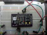
what package of LTC3108 you used?..I have one here the ssop package but i dont know what is the pin 1..the datasheet did not tell also which is pin 1.
 

what package of LTC3108 you used?..I have one here the ssop package but i dont know what is the pin 1..the datasheet did not tell also which is pin 1.

Pin 1 is VAUX. The VAUX pin powers the buffers to the JTAG pins (TCK, TMS, TDI, and TDO)
 

Pin 1 is VAUX. The VAUX pin powers the buffers to the JTAG pins (TCK, TMS, TDI, and TDO)
You are not actually talking about LTC3108, isn't it? There's no JTAG involved with this chip.
 

what package of LTC3108 you used?..I have one here the ssop package but i dont know what is the pin 1..the datasheet did not tell also which is pin 1.

Hello,

You are right. Its kind of confusing. I think its like if you can read the number on the Chip, then the lower right corner is the pin 1.

I found it through trial and error.

Hope this helps.
 
its good for you that the IC have not been damaged..thank you so much
 

Code:
You are right. Its kind of confusing. I think its like if you can read the number on the Chip, then the lower right corner is the pin 1.
I found it through trial and error.
According to the datasheet, SSOP has an unequivocal marking by a chamfered edge.
 

Code:
You are right. Its kind of confusing. I think its like if you can read the number on the Chip, then the lower right corner is the pin 1.
I found it through trial and error.
According to the datasheet, SSOP has an unequivocal marking by a chamfered edge.

nice find.

- - - Updated - - -

Sorry, my mistake, if you can read the number on the chip, its the lower left most pin that is the pin 1. Try finding the bevel edge as mentioned by FvM.
 

ltc.jpg

I so this is the net,it shows here that pin 1 is the bottom right part..i put a red mark on it,,

- - - Updated - - -

can I use through hole capacitors instead of surface mounted ones,,I don't have the values here of the surface mounted capacitors but i have the through holes.
 

Status
Not open for further replies.

Similar threads

Part and Inventory Search

Welcome to EDABoard.com

Sponsor

Back
Top