fishcake
Newbie level 4

- Joined
- Nov 4, 2012
- Messages
- 6
- Helped
- 0
- Reputation
- 0
- Reaction score
- 0
- Trophy points
- 1,281
- Activity points
- 1,345
First of all, let me state that I have very little understanding of electronics, as I just started self-learning not too long ago. So, I thought that it will be a good way to learn electronics by working on fun projects. Thus, I have decided to make a digital clock using a crystal oscillator.
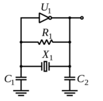
Well, at first I thought I could simply use the crystal to get some oscillation, but I later learned that I need to have some sort of circuit comprised of (2?) capacitors and resistors to actually get an oscillation (schematic obtained from this site), like so:

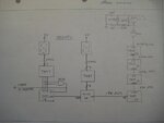
Here's another crystal oscillator circuit (from this site), which is also made to drive a digital clock:

As far as I can tell, both of these circuits are the same. So, I guess there must be some reasons as to why it must be like that. Here are my questions:
Sorry if this is a duplicate question. But to be frank, I actually searched this forum first. It's just that none of the threads I found actually helped me in understanding a crystal oscillator circuit.
Well, at first I thought I could simply use the crystal to get some oscillation, but I later learned that I need to have some sort of circuit comprised of (2?) capacitors and resistors to actually get an oscillation (schematic obtained from this site), like so:

Here's another crystal oscillator circuit (from this site), which is also made to drive a digital clock:

As far as I can tell, both of these circuits are the same. So, I guess there must be some reasons as to why it must be like that. Here are my questions:
- What is the purpose of the 2 capacitors?
- What is the purpose of the resistors? And why are there 2 really high resistors connected in series at the top? What would happen if I were to replace these 2 resistors with a lower value, like around 100K ohms (because I currently don't have resistors with such big values :sad
?
- Why are these components needed to be connected in this way (parallel)?
- Why are there 2 outputs from the oscillator circuit (connected to the 10th and 11th pin)?
- I have read somewhere about this term called "load capacitance". What does it mean? And how should I know the load capacitance of my crystal if the manufacturer/retailer doesn't provide it (**broken link removed** is what I have)?
Sorry if this is a duplicate question. But to be frank, I actually searched this forum first. It's just that none of the threads I found actually helped me in understanding a crystal oscillator circuit.
Last edited:


