Continue to Site

Welcome to EDAboard.com

Welcome to our site! EDAboard.com is an international Electronics Discussion Forum focused on EDA software, circuits, schematics, books, theory, papers, asic, pld, 8051, DSP, Network, RF, Analog Design, PCB, Service Manuals... and a whole lot more! To participate you need to register. Registration is free. Click here to register now.

Newbie: mixer's Non-linearity Testing

Status
Not open for further replies.

luckyali

Member level 5
Member level 5
Joined
Jun 6, 2011
Messages
84
Helped
2
Reputation
4
Reaction score
2
Trophy points
1,288
Location
Germany
Activity points
1,966
Hello every one.
I would like to know what tests can be performed to checked the Linearity / Non-Linearity of the the Mixer for Up-Conversion and for Down-Conversion...
 

Hello every one.
I would like to know what tests can be performed to checked the Linearity / Non-Linearity of the the Mixer for Up-Conversion and for Down-Conversion...
Hi Lucky ali

Do you have access to the spectrum analyzer ? if yes that's too easy . but if not you should use an oscilloscope with a signal generator to test it ! ( it will be a bit more time consuming in compare with doing it with a spectrum analyzer )
Best Wishes
Goldsmith
 

hi goldsmith.
Yes I do have Spectrum Analyzer(27 Ghz) and and 2 Signal Generators (40 Ghz)
 

hi goldsmith.
Yes I do have Spectrum Analyzer(27 Ghz) and and 2 Signal Generators (40 Ghz)

Mixer linearity is best tested with a power meter at IF input and RF output.
Increase IF input and follow by measuring RF output. Use one-sideband RF band-pass filter to get the desired RF output frequency only.
You will find the P-1 dB power level, when the conversion loss increases by one dB.
Typically this happens when IF input becomes ~ 7 dB lower than LO input power.

With two signal generators and spectrum analyzer, you can find the IP3, the third-order intermodulation threshold. The two input frequencies will create the intermodulation product say -2 dB below the nominal output level.

The same tests can be made on a down-converting mixer; you will need no sideband RF filter for it.

- - - Updated - - -

sorry for the misprint- it should read -20 dB below...
 

hi goldsmith.
Yes I do have Spectrum Analyzer(27 Ghz) and and 2 Signal Generators (40 Ghz)
Hi again
Another way for judgement about linearity and nonlinearity , is :
As you know a linear circuit with linear behavior won't create any unwanted harmonics . you can see the out put spectrum of your system ( instead of injecting a signal as input ) then see it's spectrum . then try to increase input level , and watch the spectrum analyzer . if unwanted harmonics are creating , it means your circuit is going to deliver nonlinear behavior .
I hope this method can help you , too .
Best Wishes and Good luck
Goldsmith
 

If i am not wrong you are talking about the Conversion gain/loss, i will also try to measure this.
How about testing other characteristics like
1. IP3
2. VSWR
3. Isolation
4. 1db compression

a little explanation will be helpful, or if someone can link a document which explain these things.
 

I have described 1. and 4. above. Isolation is measured like conversion loss but using one input signal only, and messuring ow much it reaches the other mixer port. VSWR is port matching, you can use a reflectometer for it.

What more is needed?
 

If i am not wrong you are talking about the Conversion gain/loss, i will also try to measure this.
How about testing other characteristics like
1. IP3
2. VSWR
3. Isolation
4. 1db compression

a little explanation will be helpful, or if someone can link a document which explain these things.

you need 3 signal gens for ip3 measurement
2 for input and 1 for LO
 
Last edited:

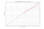
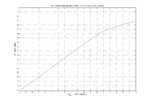
I did some measurement to check 1 db compression point. for upconversion, I applied LO= 22 Ghz with +20 dBm level, IF= 100 Mhz with power varied from -12 dBm to +12 dBm. and output at RF (22.1 Ghz) was noted for every 1dbm power change in IF...
I ploted Input IF vs output RF power levels and got this plot.
Am I correct to say that 1dB compression point is reached at +9 dBm...
HMC144_Mixer.jpg
 

Attachments

  • HMC144_Mixer.jpg
    HMC144_Mixer.jpg
    129.9 KB · Views: 132

one short question. if we want to downconvert a frequency from 22 Ghz to 3 Ghz, which setup should be applied
1. LO= 18 Ghz and RF= 22 Ghz ==> IF = RF- LO
2. LO= 22 Ghz and RF= 18 Ghz ==> IF = LO- RF

I was thinking since RF is the received signal and it is fixed, there for we have to adjust the LO frequency, but some people say that it doesn't matters to change LO or RF frequencies. the thing only matters is there difference.. |f1-f2|...
 

For option2, it should be:
LO=25GHz, RF=22GHz, so LO-RF=3GHz
 

Status
Not open for further replies.

Part and Inventory Search

Welcome to EDABoard.com

Sponsor

Back
Top