Continue to Site

Welcome to EDAboard.com

Welcome to our site! EDAboard.com is an international Electronics Discussion Forum focused on EDA software, circuits, schematics, books, theory, papers, asic, pld, 8051, DSP, Network, RF, Analog Design, PCB, Service Manuals... and a whole lot more! To participate you need to register. Registration is free. Click here to register now.

Problem with MPLAB with CCS Compiler code

Status
Not open for further replies.

Papizo

Junior Member level 1
Joined
Feb 3, 2012
Messages
18
Helped
1
Reputation
2
Reaction score
1
Trophy points
1,283
Activity points
1,443
Hi guys am doing this project Vehicle security system with theft control and Accident Notification so before I start anything I want to test my PIC16F877A if is going to work with CCS C, so I want to test my 2 LED blinking I have found program online which will work but is not working at all

main.c

Code C - [expand]
1
2
3
4
5
6
7
8
9
10
11
12
13
14
15
16
17
18
19
20
21
22
23
24
25
26
27
28
29
30
31
32
33
34
35
36
37
38
39
40
41
42
43
44
45
46
47
48
49
50
51
52
53
54
55
56
57
58
59
60
61
62
63
64
65
66
67
68
69
70
71
72
73
74
75
76
77
78
79
80
81
82
83
84
85
86
87
88
89
90
91
92
93
94
95
96
97
98
99
100
101
102
103
104
105
106
107
108
109
110
111
112
113
114
115
// PIC16F877A LED Blinking      
//===============================================================
 
//device definition header file
#include <16F877A.h>
#include "htc.h"
 
//device configuration bit
__CONFIG(0x3F3A);
 
//define
#define LED1    RB7
#define LED2    RB6
 
//function prototype
void blink_LED1(unsigned char n);
void blink_LED2(unsigned char n);
 
//main function
//================================================================
void main(void)
{
    //device peripheral configuration
    TRISB7=0;       //set RB7 as output
    TRISB6=0;       //set RB6 as output
    
    //infinity loop
    while(1)
    {
        //blink LED1 for 3 times
        blink_LED1(3);
        
        //blink LED2 for 3 times
        blink_LED2(3);
    }
}
 
//function to blink LED1 for n times
void blink_LED1(unsigned char n)
{
    //loop for n times
    for(n+=1;n>0;n-=1)
    {
        //set LED1 to 1
        LED1=1;
        
        //short delay
        for(unsigned int i=0;i<20000;i+=1);     //max value is 65535
            
        //set LED1 to 1
        LED1=0;
        
        //short delay
        for(unsigned int i=0;i<20000;i+=1);     //max value is 65535            
    }   
}
 
//function to blink LED2 for n times
void blink_LED2(unsigned char n)
{
    //loop for n times
    for(n+=1;n>0;n-=1)
    {
        //set LED2 to 1
        LED2=1;
        
        //short delay
        for(unsigned int i=0;i<20000;i+=1);     //max value is 65535
            
        //set LED2 to 1
        LED2=0;
        
        //short delay
        for(unsigned int i=0;i<20000;i+=1);     //max value is 65535            
    }       
}   
 
 
header filer
 
 
//===============================================================
//device definition header file
#include <htc.h>
 
//device configuration bit
__CONFIG(0x3F3A);
 
 
//define
#define LED1    RB7
 
//main function
//================================================================
void main(void)
{
    //device peripheral configuration
    TRISB7=0;
    
    //infinity loop
    while(1)
    {
        //set LED1 to 1
        LED1=1;
        
        //short delay
        for(unsigned int i=0;i<30000;i+=1);
        
        //set RB7 to 0
        LED1=0;
        
        //short delay
        for(unsigned int i=0;i<30000;i+=1);
    }
}


so when am trying to compile getting this error
Clean: Deleting intermediary and output files.
Clean: Done.
Executing: "C:\Program Files (x86)\PICC\Ccsc.exe" "main.c" +FM +DF +LN +T -A +M +Z +Y=9 +EA
*** Error 17 "C:\Users\User\Desktop\mplab\htc.h" Line 4(10,11): Too many nested #INCLUDEs
1 Errors, 0 Warnings.
Halting build on first failure as requested.
BUILD FAILED: Fri Oct 26 14:26:32 2012

So what is the problem with my code? can you show me where I have done wrong please...
 
Last edited by a moderator:

Hi Papizo, the problem is that code is not for CCS C compiler. Of course you can adapt it, but if you have the CCS C compiler installed in your PC, use the wizard to create a simple program for a blinking LED.

Cheers!
 
  • Like
Reactions: Papizo

    Papizo

    Points: 2
    Helpful Answer Positive Rating
connect 2 leds to microcontroller pins RB6 and RB7 with proper resistor value.
try this in ccs. It will work.
HTML:
#include "16F877A.h"
#fuses HS, INTRC_IO
#use delay(clock = 4000000)            //  4MHZ internal clock

#define LED1    RB7
#define LED2    RB6

void main()
{
   setup_oscillator(OSC_4MHZ);
   while(1)
   {
      output_high(LED1);            
      delay_ms(100);               
      output_high(LED2);             
      delay_ms(100);                  
   }
}

Best Wishes.
 
  • Like
Reactions: Papizo

    Papizo

    Points: 2
    Helpful Answer Positive Rating
Hi Papizo, the problem is that code is not for CCS C compiler. Of course you can adapt it, but if you have the CCS C compiler installed in your PC, use the wizard to create a simple program for a blinking LED.

Cheers!

Thank you for your help bro, Actual am mistaken my self,what I was planning to say is am using MPLAB with Pickit 2, also with my project am using PIC16F877A so for MPLAB I have to use CCS C language and not compiler, I need your help please if possible. I have never use CCS C compiler before, also if I use it how will I damp the code to my PIC16F877A because I cant use pickit 2 in CCS compiler, I will be happy if someone give me more informations.

- - - Updated - - -

connect 2 leds to microcontroller pins RB6 and RB7 with proper resistor value.
try this in ccs. It will work.
HTML:
#include "16F877A.h"
#fuses HS, INTRC_IO
#use delay(clock = 4000000)            //  4MHZ internal clock

#define LED1    RB7
#define LED2    RB6

void main()
{
   setup_oscillator(OSC_4MHZ);
   while(1)
   {
      output_high(LED1);            
      delay_ms(100);               
      output_high(LED2);             
      delay_ms(100);                  
   }
}

Best Wishes.

Hi thank you a lot for your help, so if I put this code on my CCS C how will I dump the code to my PIC16877A because CCS C compiler is not accepting pickit 2 right??I need more help ad explanation please if possible because am new to this.
 

Hello Papizo, you can use many compilers with MPLAB including the CCS C compiler. You must first download from the CCS page a plugin named "MPLAB®IDE Plug-in" which lets you use the CCS compiler within the MPLAB. Then, you can try to compile the hemnath's code and after that you can download it to the microcontroller through the PICkit2, all this within the MPLAB IDE. If you can, I recommend you get a book called: "PICmicro® MCU C An Introduction to Programming the Microchip PIC in CCS C"

Best Wishes!
 
  • Like
Reactions: Papizo

    Papizo

    Points: 2
    Helpful Answer Positive Rating
can you please tel me your mplab version?
ofcourse you can dump the code from mplab via pickit 2 programmer to the microcontroller what you use. mplab 8.87 and it supports pickit 2. "also keep note on previous comment said by bmb_10". you must install mplab plugin. if you have installed all these you can easlily communicate to your micro controller.

Also there is an another option, if your current mplab version doesn't supports pickit 2, download pickit 2 v2.61 and install it. It is seperate software. compile the code in mplab with ccs c compiler. and hex file will gets generated. Plug in pickit 2 usb to your system, and double-click the installed pickit2 v2.61 which opens the dialog box. import hex file and program.

Best wishes.
 
  • Like
Reactions: Papizo

    Papizo

    Points: 2
    Helpful Answer Positive Rating
Hello Papizo, you can use many compilers with MPLAB including the CCS C compiler. You must first download from the CCS page a plugin named "MPLAB®IDE Plug-in" which lets you use the CCS compiler within the MPLAB. Then, you can try to compile the hemnath's code and after that you can download it to the microcontroller through the PICkit2, all this within the MPLAB IDE. If you can, I recommend you get a book called: "PICmicro® MCU C An Introduction to Programming the Microchip PIC in CCS C"

Best Wishes!

Thank you for your help, yes I have already downloaded "MPLAB®IDE Plug-in", and also I have tried to compile the code but am getting error so any solution I will appreciate, or the problem is my CCS C compiler the way I installed??

- - - Updated - - -

can you please tel me your mplab version?
ofcourse you can dump the code from mplab via pickit 2 programmer to the microcontroller what you use. mplab 8.87 and it supports pickit 2. "also keep note on previous comment said by bmb_10". you must install mplab plugin. if you have installed all these you can easlily communicate to your micro controller.

Also there is an another option, if your current mplab version doesn't supports pickit 2, download pickit 2 v2.61 and install it. It is seperate software. compile the code in mplab with ccs c compiler. and hex file will gets generated. Plug in pickit 2 usb to your system, and double-click the installed pickit2 v2.61 which opens the dialog box. import hex file and program.

Best wishes.

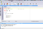
My MPLAB is version 8.63, also I have already download the pickit v2.61, also about mplab plugin I have installed that from the beginning, also my current mplab version it supporting pickit 2 so I don't know know why I cant compile... I have attached two screenshot for my testing....Hope I will get more help....
 

Attachments

  • test2.png
    test2.png
    173 KB · Views: 226
  • Test.png
    Test.png
    117.1 KB · Views: 191
Last edited:
  • Like
Reactions: bmb_10

    bmb_10

    Points: 2
    Helpful Answer Positive Rating
Thank you for your help, yes I have already downloaded "MPLAB®IDE Plug-in", and also I have tried to compile the code but am getting error so any solution I will appreciate, or the problem is my CCS C compiler the way I installed??


Hi, what error is showing the compiler? Which version of CCS you have?

Greetings!

Sorry, had not seen the image of the errors. Try this code:

Code:
#include <16F877A.h>

#FUSES NOWDT                    //No Watch Dog Timer
#FUSES XT                       //Crystal osc <= 4mhz for PCM/PCH , 3mhz to 10 mhz for PCD
#FUSES NOBROWNOUT               //No brownout reset
#FUSES NOLVP                    //No low voltage prgming, B3(PIC16) or B5(PIC18) used for I/O

#use delay(clock=4)

#define LED1 PIN_B6
#define LED2 PIN_B7
#define DELAY 500

void main()
{

   //Example blinking LED program
   while(true)
   {
      output_low(LED1);
      delay_ms(DELAY);
      output_high(LED2);
      delay_ms(DELAY);
      output_low(LED2);
      delay_ms(DELAY);
      output_high(LED1);      
      delay_ms(DELAY);     
   }
}

I hadn't remember that the PIC16F877A has no internal oscillator. You must use a 4MHz crystal.
 
Last edited:
  • Like
Reactions: Papizo

    Papizo

    Points: 2
    Helpful Answer Positive Rating
Hi, what error is showing the compiler? Which version of CCS you have?

Greetings!

Sorry, had not seen the image of the errors. Try this code:

Code:
#include <16F877A.h>

#FUSES NOWDT                    //No Watch Dog Timer
#FUSES XT                       //Crystal osc <= 4mhz for PCM/PCH , 3mhz to 10 mhz for PCD
#FUSES NOBROWNOUT               //No brownout reset
#FUSES NOLVP                    //No low voltage prgming, B3(PIC16) or B5(PIC18) used for I/O

#use delay(clock=4)

#define LED1 PIN_B6
#define LED2 PIN_B7
#define DELAY 500

void main()
{

   //Example blinking LED program
   while(true)
   {
      output_low(LED1);
      delay_ms(DELAY);
      output_high(LED2);
      delay_ms(DELAY);
      output_low(LED2);
      delay_ms(DELAY);
      output_high(LED1);      
      delay_ms(DELAY);     
   }
}

I hadn't remember that the PIC16F877A has no internal oscillator. You must use a 4MHz crystal.

Hi bmb_10

Thank you for your help, I have tried to compile the code and worked fine, in CCS C compiler and even in MPLAB, so my question is that because I have already build PIC16F877A in veroboard with 20 Crystal osc so on that code can change to 20 MHz instead of 4 MHz??
 

Hi papizo, if you want to work with a 20MHz crystal, you need to change two things in the code. You must first change the fuse: XT by HS and second you must change the instruction: #use delay(clock= 4M) by: #use delay(clock= 20M) or #use delay(clock= 20000000). Are you looking for the book? I would highly recommend it to you to learn the foundations of the CCS and the C language in general.

Greetings!
 
  • Like
Reactions: Papizo

    Papizo

    Points: 2
    Helpful Answer Positive Rating
Hi papizo, if you want to work with a 20MHz crystal, you need to change two things in the code. You must first change the fuse: XT by HS and second you must change the instruction: #use delay(clock= 4M) by: #use delay(clock= 20M) or #use delay(clock= 20000000). Are you looking for the book? I would highly recommend it to you to learn the foundations of the CCS and the C language in general.

Greetings!

Hi bmp_10

Thank you for your help appreciate, also I will do testing tomorrow then I will give you feedback as soon as possible, also I have got that book already...Again thank you, if I have anything I will keep posting on this thread.....
 

Hi bmb_10 and hemnath ,

Thank you guys for your help,I have tested the code with LED and worked fine without any problem thank you a lot...Actual I will be around to ask more question if I have on this thread...
 

Hi Papizo, I'm very glad that now you're on your way to learning the language C. Do not hesitate to ask what you need.

Greetings!
 
  • Like
Reactions: Papizo

    Papizo

    Points: 2
    Helpful Answer Positive Rating
Hi Papizo, I'm very glad that now you're on your way to learning the language C. Do not hesitate to ask what you need.

Greetings!

Hi am back again, and that book you recommended me to use it helps a lot, thank you again, Also I wanted to create Schematic diagram but I can't use Multisim because I cant find PIC16F877A, Also I have tried to use ExpressSCH but still I cant find all component am looking, so which software can I use to create my Schematic, Any help??please??
 

Use proteus. It will be very useful to you.

best wishes :)
 
  • Like
Reactions: Papizo

    Papizo

    Points: 2
    Helpful Answer Positive Rating
Use proteus. It will be very useful to you.

Hello Papizo, I agree with hemnath. If you decide to go with Proteus, I would recommend getting a book called "CCS C Compiler and Simulator Proteus for PIC Microcontrollers" which brings a CD with examples. This will serve you both to learn something of CCS as to learn Proteus.

Greetings!
 
  • Like
Reactions: Papizo

    Papizo

    Points: 2
    Helpful Answer Positive Rating
Use proteus. It will be very useful to you.

best wishes :)

Thank you Hemnath, I have tried to check proteus PIC16F877A I can't find pin 11, 32 and 12, 32 what should I do??

- - - Updated - - -

Hello Papizo, I agree with hemnath. If you decide to go with Proteus, I would recommend getting a book called "CCS C Compiler and Simulator Proteus for PIC Microcontrollers" which brings a CD with examples. This will serve you both to learn something of CCS as to learn Proteus.

Greetings!

Thank you bmp_10, yes I will get that book as well and it will me..... because I have a lot to do with GSM and GPS as well, but I will ask more questions here.......Thank you again
 

Thank you Hemnath, I have tried to check proteus PIC16F877A I can't find pin 11, 32 and 12, 32 what should I do??

Hello Papizo, it is normal that Proteus does not show the power pins because Proteus automatically connects these pins to the power buses VDD and VSS. There is an option to view these pins by clicking on Menu -> Templates -> Set Design Defaults ... -> Show Hidden Pins. The strange thing is that I did the test with some ICs and it works well, but the PIC16F877A doesn't work to me any way. Perhaps someone else can tell us how to view these pins in that PIC.

Greetings!
 
  • Like
Reactions: Papizo

    Papizo

    Points: 2
    Helpful Answer Positive Rating
Hello Papizo, it is normal that Proteus does not show the power pins because Proteus automatically connects these pins to the power buses VDD and VSS. There is an option to view these pins by clicking on Menu -> Templates -> Set Design Defaults ... -> Show Hidden Pins. The strange thing is that I did the test with some ICs and it works well, but the PIC16F877A doesn't work to me any way. Perhaps someone else can tell us how to view these pins in that PIC.

Greetings!

Yes me too I have tried as well but its not working with PIC16F877A.....I have tried different pic but I can see the VDD and VSS...
 

Well it is. But finally, for what you want to see the pins? If you click on the microcontroller, and then you click on the button 'Hidden Pins' you can see that buses are connected these pins, so you don't have any problem to make a simulation, unless what you want would be to produce an schematic of your circuit.

Greetings!
 
  • Like
Reactions: Papizo

    Papizo

    Points: 2
    Helpful Answer Positive Rating
Status
Not open for further replies.

Similar threads

Part and Inventory Search

Welcome to EDABoard.com

Sponsor

Back
Top