Continue to Site

Welcome to EDAboard.com

Welcome to our site! EDAboard.com is an international Electronics Discussion Forum focused on EDA software, circuits, schematics, books, theory, papers, asic, pld, 8051, DSP, Network, RF, Analog Design, PCB, Service Manuals... and a whole lot more! To participate you need to register. Registration is free. Click here to register now.

Pure Sine wave inverter microprocessor based and transformerless

Status
Not open for further replies.

fadapow

Newbie level 5
Newbie level 5
Joined
Oct 10, 2012
Messages
8
Helped
1
Reputation
2
Reaction score
1
Trophy points
1,283
Activity points
1,346
I am designing an inverter for a diy project. This inverter should be transformer-less and microprocessor based. I am planning to use a DC-DC converter, but should i used a the Peak voltage or the RMS for the DC-DC output, and how do i configure the circuit to handle the power i have in mind? How could I limit the device to....say 250W , with a 24v input, the input current would be, 10.42A, how would i ensure that the output is say, 2.1A?

Thanks
 

Hi fadapow,
1. You should take the RMS voltage
2. You can limit the power output by measuring the output current and feeding it to the controller and write appropriate code.
Hope you found this useful if so click the helped me button below
regards ani
 
Thanks for your reply picgak. You mentioned writing appropriate code, but i am wondering if the controller will be able to handle that much power, i am considering a 120 VAC output @ 200W using PWM.
 

Surely the micro controller can handle it
 
I am designing an inverter for a diy project. This inverter should be transformer-less and microprocessor based. I am planning to use a DC-DC converter, but should i used a the Peak voltage or the RMS for the DC-DC output,

The output of the DC-DC converter has to be greater than the peak voltage of the output sine wave.

and how do i configure the circuit to handle the power i have in mind? How could I limit the device to....say 250W , with a 24v input, the input current would be, 10.42A, how would i ensure that the output is say, 2.1A?

Thanks

Use the microcontroller to detect the amount of current flowing through. If it is greater than the reference current, shut down the PWM to turn the inverter off.

but i am wondering if the controller will be able to handle that much power, i am considering a 120 VAC output @ 200W using PWM.
The microcontroller won't be the one "taking" the power, so it can control for 200W easily. Why only 200W? It can control for much higher powers as well, if necessary.

Hope this helps.
Tahmid.
 
please help me,
how to increase the output voltage without a choke or transformer............?
 

matthai your question is not clear

- - - Updated - - -

matthai your question is not clear
 

what you mean by transformer less....?
how to convert 24v 120v without a transformer...?
 

Instead of completely transformerless, why not use a ferrite core transformer? It's smaller and cheaper for the same power. Then, you can make a DC-DC converter with it. Convert the high voltage DC to AC with a full-bridge converter.
 
Thank you very much Tahmid, your suggestions and replies are truly appreciated. However, as to why transformerless, I want to take on the challenge of designing one, i saw this really small inverter and instantly i wanted to make one of my own. So my aim is to limit the use of analague components as much as possible. So here is the overview of the project i have in mind.
12/24V DC input,
using a dc-dc converter, boast the voltage greater than the peak voltage of the output sine wave,
then use PWM with the micro-controller to generate the pure sine wave (using relevant filtering if necessary to reduce THD).

Feel free to correct me where i'm wrong
 

An smps with ferite transformer should be used for converting Battery voltage to the voltage required for the final H bridge
 
I have been busy for a while, but its time to continue my project.
OK, so for the DC-DC stage, i guess a full-bridge boost topology should be OK, and what would be the ideal switching device to use for the intended power range, and also the PWM frequency for the DC-DC stage?
 

I have been busy for a while, but its time to continue my project.
OK, so for the DC-DC stage, i guess a full-bridge boost topology should be OK, and what would be the ideal switching device to use for the intended power range, and also the PWM frequency for the DC-DC stage?
It all depend on your designed,push pull is normally used for dc-dc stage and H-bridge for the final output and the dc-dc pwm you can used 38-40khz .
 

I have been busy for a while, but its time to continue my project.
OK, so for the DC-DC stage, i guess a full-bridge boost topology should be OK, and what would be the ideal switching device to use for the intended power range, and also the PWM frequency for the DC-DC stage?

You can use the full-bridge to drive the ferrite transformer and another full-bridge at the high voltage DC side to convert the DC to 50Hz AC.

For DC-DC, you can use between 30kHz and 100kHz. You can try with 50kHz. The higher the frequency the smaller the required magnetic components, but the higher the switching losses.

For the sinusoidal PWM (SPWM), you can use a modulation frequency between 4kHz and 70kHz. The higher the frequency the smaller the required inductance and capacitance, but the higher the switching losses. I usually use 16kHz to 24kHz.

Hope this helps.
Tahmid.

Thanks again Tahmid, you are truly a life saver. But i am wondering if I have to use an isolated dc-dc converter, why exactly cant I, or why is it not recommended to use to non-isolated dc-dc converter, I am still trying to make this design as small and efficient as possible. As you mentioned, smaller components can be used but with a higher switching frequency which in turn increases the losses in the design, I am thinking that since the ferite core would be an additional component this converter will have a greater than if i use just the non-isolated design.
 

If you don't use a transformer, you'll have to use a boost converter. The voltage stress on the MOSFET will be atleast the output voltage. Peak currents will be too high. Vout = Vin when MOSFET is off. You will tend to have too high losses. Since you'll need to use an inductor anyways for boost converter, just use a transformer instead and use a push-pull or full-bridge converter. You will have a better circuit.

If size is a concern, increase switching frequency so that you need smaller magnetic components. If size is the priority, you will have to deal with the higher switching losses to reduce the size.

Hope this helps.
Tahmid.
 
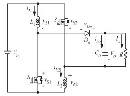
Thanks again for your help, however i came across a switched-inductor dc boost converter topology, i have attached the circuit below, can this be used instead of the isolated push-pull or full-bridge topology? I am still determined to make this device as small as possible, i know that i will still have to deal with the high switching loss if I increase the frequency, and increase the components size if it is lower, but is there any advantage of using the topology i found over the others? Thanks in advance.

1605444700_1355455448.jpg
 

Status
Not open for further replies.

Similar threads

Part and Inventory Search

Welcome to EDABoard.com

Sponsor

Back
Top