Continue to Site

Welcome to EDAboard.com

Welcome to our site! EDAboard.com is an international Electronics Discussion Forum focused on EDA software, circuits, schematics, books, theory, papers, asic, pld, 8051, DSP, Network, RF, Analog Design, PCB, Service Manuals... and a whole lot more! To participate you need to register. Registration is free. Click here to register now.

HFSS Eigenmode and Wavenumber

Status
Not open for further replies.

JohnFid

Junior Member level 3
Joined
Oct 22, 2012
Messages
29
Helped
2
Reputation
4
Reaction score
2
Trophy points
1,283
Location
Greece
Activity points
1,474
Hello, I am trying to implement a periodic cell for antenna design and I want to produce a diagram Frequency Vs Wavenumber in eigenmode. How can I import wavenumber to my design? As I know, HFSS use ko, wavenumber in free space of each mode to calculate resonation frequency. Thank you.
 

I assume by wave number (k), which is effectively constant, you mean the phase "constant" β.

This can be achieved by implementing a variable angle into the master/slave boundaries of your eigenmode simulation, where this Angle = β*d, where d is the length of your cell. I've written instructions on this forum before - check out https://www.edaboard.com/threads/265560/#post1140645

Good Luck
 
Kx=bx-jax according to the paper...and kx is from 0 to 1800..What exactly value do i have to put on the delay? it must be multiple to 180 or 360? ax is attenuation constant and bx phase constant
 

Kx=bx-jax according to the paper

Called the propagation constant where I come from, but I get what you're saying.

What exactly value do i have to put on the delay?

The delay is a phase delay, I.E. and angle. It repeats itself every 180 degrees, so you want to sweep 0-180
 
The delay is a phase delay, I.E. and angle. It repeats itself every 180 degrees, so you want to sweep 0-180
But how I get the diagram for kx = 0:1800?
This is the project:
View attachment cell2.zip
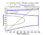
and this is what I trying to produce:
Untitled.jpg
If you have time please take a look..
 
Last edited:

Hi John,

I understand now, it's k_x, not k*x. This is just the phase constant (β) to which I was referring - so what you need to do is take my equation Angle = β*d, and get β = Angle/d.

This is the tricky part - it doesn't give units for k. It could be rad/m or degrees/m. It appears to be radians, from the graph title, so you would sweep from 0 degrees to

Angle = 1800*(pi/180)*(d)

However, to be thorough, you should really just sweep 0 - 180 degrees. This might be the same case if your unit cell is the proper size, however.
 
First of all, thank you for your immediate answer.
If I understand, I will create a variable k_x which will vary from 0 to 1800 (sweep) and the phase delay will be Angle = k_x * (pi/180) * d?
I tried sweeping from 0 to 180 deg but the results wasn't the same.. :(
 

If I understand, I will create a variable k_x which will vary from 0 to 1800 (sweep) and the phase delay will be Angle = k_x * (pi/180) * d?

Yes, I believe that is correct.

I'm sorry that your results didn't turn out. Sweeping 0-180 should give you all the information there is to obtain. However, there are numerous simulation settings to account for. You may want to check:

Minimum Frequency
Number of Modes
Convergance (Δf)
$Angle Step Size

Good Luck
 
Thank you very much, PlanarMetamaterials. I had some erorrs on my design but I fixed them. It seems to work now.
The results are very similar to that on paper. :)
 
Status
Not open for further replies.

Similar threads

Part and Inventory Search

Welcome to EDABoard.com

Sponsor

Back
Top