Continue to Site

Welcome to EDAboard.com

Welcome to our site! EDAboard.com is an international Electronics Discussion Forum focused on EDA software, circuits, schematics, books, theory, papers, asic, pld, 8051, DSP, Network, RF, Analog Design, PCB, Service Manuals... and a whole lot more! To participate you need to register. Registration is free. Click here to register now.

Voltage Controlled PWM using OP-Amp

Status
Not open for further replies.

halee awan

Full Member level 3
Full Member level 3
Joined
Apr 8, 2006
Messages
151
Helped
11
Reputation
22
Reaction score
11
Trophy points
1,298
Activity points
2,207
Hi,

Anyone who has experience with that how to get a PWM signal whose Puls should be controlled based one the I/P voltage ±5V Using simple OP-Amp ?
Thanks in advance
 

Hi

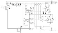
For some years ago i designed a PWM board with simple components, to demonstrate the basic principle for generating a PWM signal. The board was a part of a complete DC motor controller build from scratch.


The input voltage range is not what you describe, but you can make a few changes to the schematic, to adapt it to your voltage levels.

H.E.Tjelum
 
thanks to you all
I'd designed this Hardware for some specific task and i used 555 timer
for ±5V supply I used absolute cct using Op-Amp so its Works for me
 

Attachments

  • Schematic.pdf
    46.2 KB · Views: 199

Status
Not open for further replies.

Similar threads

Part and Inventory Search

Welcome to EDABoard.com

Sponsor

Back
Top