Welcome to our site! EDAboard.com is an international Electronics Discussion Forum focused on EDA software, circuits, schematics, books, theory, papers, asic, pld, 8051, DSP, Network, RF, Analog Design, PCB, Service Manuals... and a whole lot more! To participate you need to register. Registration is free. Click here to register now.
hi,
after the CT you put rezistor as a load, a precision rectifier + some signal conditioner circuit, and you can conect directly the microcontrollers ADC.
;-)
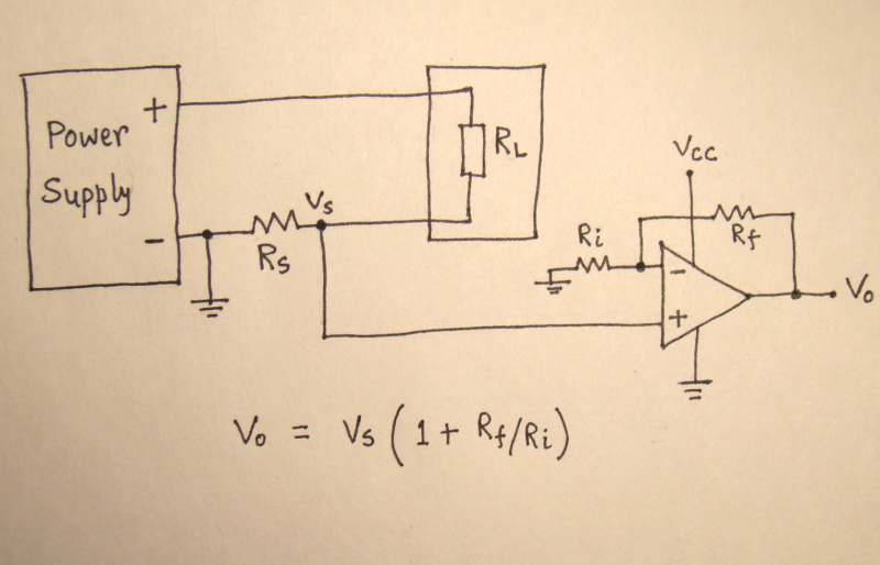
This circuit is completely functional with DC and AC measurements.
If you want to sense frecuency and peak voltage (proportional to the current in the load) you can try this technique of an application note from Atmel: http://www.atmel.com/Images/doc2508.pdf
So you can have an interrupt each time the sinusoidal signal crosses zero. Using simple maths you can use the microcontroller ADC to save the magnitude of the voltage exactly at the point to measure the maximum value (peak). And there you have, a very cheap AC/DC current sensor.
Thank you all for sharing your knowlege. What I want is to use a cuurent transformenr to measure AC current rangiung from 0- 100A while keeping total isolation from main circuit. Think I can use Current transformer, burdon resistor and precision ractfier cisrcuit to get current value. Does average voltage output of precision rectfier give proportional value to the current flowing in the conductor ?
Do I need to sample voltage output of OP amp and get RMS value ?
This site uses cookies to help personalise content, tailor your experience and to keep you logged in if you register.
By continuing to use this site, you are consenting to our use of cookies.