Continue to Site

Welcome to EDAboard.com

Welcome to our site! EDAboard.com is an international Electronics Discussion Forum focused on EDA software, circuits, schematics, books, theory, papers, asic, pld, 8051, DSP, Network, RF, Analog Design, PCB, Service Manuals... and a whole lot more! To participate you need to register. Registration is free. Click here to register now.

[SOLVED] Amplifier (+frequency response) ??? homework

Status
Not open for further replies.

requester

Newbie level 6
Newbie level 6
Joined
Oct 7, 2012
Messages
12
Helped
0
Reputation
0
Reaction score
0
Trophy points
1,281
Activity points
1,384
Hi,

We have a homework task to create an amp that will amplify 200mV to 2V over a load of 10kOhms.
I'm using this forum as a very last resort to get some straightforward help in the form of a full circuit.

The function generator is supposed to operate at 1kHz (200mV). That's about all I know. Any effort in trying to find formula's to calculate the capacitors is turning into waste of time.

More information: I believe the transistor amplifier must be a common-emitor one. As transistor we were obliged to use a BC547.
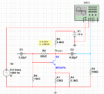
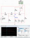
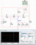
Multisim circuit looks currently like this:
current_lab.JPG

Again, my question is not to assist with any detours .... I need (and sorry for speaking out of place) a working circuit with a correct Q-point and perfect amplifying operation (200mV -> 2V).

If anyone can assist in the next few hours, please! It'd be a miracle.

Thank you in advance!

PS: if any more information is required, I am here to assist.
 

Here, you can play around with this. Seems to meet your basic specification.
 

Attachments

  • amp.gif
    amp.gif
    87.6 KB · Views: 123
  • amp1.gif
    amp1.gif
    15.2 KB · Views: 128
@chuckey: What's your value for C1?
@E-design: you replace a capacitor with a resistor?
 

LOOKS ABOUT RIGHT, 6MF?
Frank

I'm sorry, I'm not englishly rooted :p so didn't read it the right way. Thanks for your help! I got different but right values I think.

greetings
 

@E-design: you replace a capacitor with a resistor?

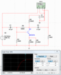
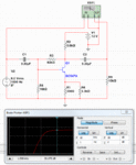
Your specification wanted a certain gain figure at 1kHz with a 10k load. C1 and C3 (in your diagram) will affect your low frequency cut-off. The value is not that critical as long as it does not affect your gain at 1kHz. For this design 0.22uF is adequate as can be seen from the bode plots.
If we used 0.1uF that would have resulted in a slight gain loss. Using 6uF capacitors would have allowed you the desired gain down to about 30Hz. If your load value was lower then accordingly the capacitor value need to increase.

This transistor has plenty of available gain at 1kHz, so the emitter bypass capacitor is not needed in this design. R1 and R6 is in parallel to get close to the value needed to satisfy the gain requirement using standard values.
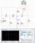
You will add this bypass capacitor to compensate for gain loss at higher frequencies.

For example if you look at the HF side you will see the gain starts to drop around 5MHz. If we add a 27pF emitter bypass we can keep the gain constant up to about 25MHz
 

Attachments

  • bode100n.gif
    bode100n.gif
    44.7 KB · Views: 138
  • bode220n.gif
    bode220n.gif
    46.4 KB · Views: 115
  • bode6u.gif
    bode6u.gif
    44.9 KB · Views: 124
  • bode5M.gif
    bode5M.gif
    43.1 KB · Views: 124
  • bode25M.gif
    bode25M.gif
    45.8 KB · Views: 124
Last edited:
Many thanks to everyone for all the help. Some came a bit late for the task at hand but I learned more than I could wish for!
@E-design: I might need your help in the near future ;) if that's ok.
@countmybones: It looks very very informative, I'll take a closer look soon.

Thanks again all!
 

Status
Not open for further replies.

Part and Inventory Search

Welcome to EDABoard.com

Sponsor

Back
Top