Continue to Site

Welcome to EDAboard.com

Welcome to our site! EDAboard.com is an international Electronics Discussion Forum focused on EDA software, circuits, schematics, books, theory, papers, asic, pld, 8051, DSP, Network, RF, Analog Design, PCB, Service Manuals... and a whole lot more! To participate you need to register. Registration is free. Click here to register now.

Noise Figure and impedance matching probelms with LNA

Status
Not open for further replies.

hhxuexia

Newbie level 6
Newbie level 6
Joined
Nov 1, 2009
Messages
11
Helped
0
Reputation
0
Reaction score
0
Trophy points
1,281
Activity points
1,365
hi,

I am designing a low noise amplifier with the structure shown below. The impedance of port1 is 50 ohm.


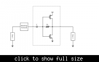
1. when I change the impedance of port2 from 50 ohm to 100 ohm, the voltage gain from port1 to port2 inreases, but noise figure(NF) remains the same. I am confused with it, since the gain changes, why noise figure does not change at all?
2. if the input impedance of LNA(circuits in dashed block) is exactly 50 ohm, then do we still need the impedance matching network?

Thansk!
 

You may know that the actual noise figure of an active device depends on the source impedance. When parasitic capacitance/inductance can be ignored, optimum source impedance depends on the noise current and voltage (all transfered to the input of the active device). So changing the load impedance may change gain, but effect on F can be small.

Mostly Zs(optimum noise) <> input impedance of active device. So matching a device for maximum power gain, does mostly not result in lowest noise figure (F). By using feedback, one can modify the input impedance of the amplifier (=active device + surrounding components) to get the desired input impedance.

When Rf is not very large with respect to Zs, it will contribute some noise to the input (hence reducing the noise figure). When you change ZL, the voltage gain (not insertion voltage gain) of the amplfiier changes, hence the current through Rf and the amplifier's input impedance.

When Zs=50 Ohms gives the desired noise figure and due to the feedback the input impedance of the amplifier = 50 Ohms, you don't need matching.
 

Hi, WimRFP!

Thanks for your reply.
It seems you are talking about noise matching in the first and second paragraphs, changing load impedance also change the equivalent noise voltage and current source at the input of LNA, and source impedance need to change for minimum noise figure(NFmin), and this NFmin also changes due to the change of load impedance.

in my case, i just changed the load impedance(impedance of port2), not other things. And the result is, voltage gain changes, but noise figure does not change a little at all. I want to know, why noise figure remains the same? Thanks!

You may know that the actual noise figure of an active device depends on the source impedance. When parasitic capacitance/inductance can be ignored, optimum source impedance depends on the noise current and voltage (all transfered to the input of the active device). So changing the load impedance may change gain, but effect on F can be small.

Mostly Zs(optimum noise) <> input impedance of active device. So matching a device for maximum power gain, does mostly not result in lowest noise figure (F). By using feedback, one can modify the input impedance of the amplifier (=active device + surrounding components) to get the desired input impedance.

When Rf is not very large with respect to Zs, it will contribute some noise to the input (hence reducing the noise figure). When you change ZL, the voltage gain (not insertion voltage gain) of the amplfiier changes, hence the current through Rf and the amplifier's input impedance.

When Zs=50 Ohms gives the desired noise figure and due to the feedback the input impedance of the amplifier = 50 Ohms, you don't need matching.
 

My first paragraph discusses the noise voltage and currents, these are device dependent, and these determine the noise behavior. The last sentence of my first paragraph mentions that changing load impedance has affect on gain, but small effect on F.

You may visit https://www.eng.auburn.edu/~wilambm/pap/2011/K10147_C011.pdf After the introduction to noise, chapter 11.3 and further discussen the noise sources in the BJT, JFET and MOSFET. You can transfer all sources to the input (gate or base) and this results in a voltage noise source in series and a current noise source in parallel with the input (say gate or base). As you can see from the math, Zload is not present in the equations.
 
Status
Not open for further replies.

Part and Inventory Search

Welcome to EDABoard.com

Sponsor

Back
Top