Continue to Site

Welcome to EDAboard.com

Welcome to our site! EDAboard.com is an international Electronics Discussion Forum focused on EDA software, circuits, schematics, books, theory, papers, asic, pld, 8051, DSP, Network, RF, Analog Design, PCB, Service Manuals... and a whole lot more! To participate you need to register. Registration is free. Click here to register now.

battery connect to my circuit automatically when main power disconnected

Status
Not open for further replies.

meysam_abbasinia

Advanced Member level 4
Full Member level 1
Joined
Aug 14, 2007
Messages
105
Helped
2
Reputation
4
Reaction score
2
Trophy points
1,298
Location
IRAN
Activity points
2,136
hi friends

I design a circuit that need work with main power and backup battery, when main power disconnected i need backup battery supply my circuit automatically. my battery is 12V and main power is 13.8V and i need when return main power battery charging started and after raise it's voltage to 12V battery charge stop.
my battery is Sealed Lead Acid.

thank you.
 

You didn't say how much current you needed.
If you want something simple, then you could try this.
I didn't need much current. It's not sophisticated but I was in a hurry,
and is enough for supplying a couple of amps from memory. It doesn't include any charging.
backup_supply.jpg
 

this circuit is very simple and don't have any method for charge battery.
my current is 2A.
 

At 2A, then the circuit above will be fine. Charging can be as simple as a diode and resistor, if you want to indefinitely trickle charge
your lead acid cell (not that I'm an expert at that).
 

If the maximum load current is below allowed/intended battery charge current, simple parallel operation of battery and voltage/current limited main power supply is the best option for lead-acid battery. It's used in most backup battery circuits, e.g. for burglar alarms.

You won't be able to charge a battery with only 12V, the required charging voltage of 13.8 - 14.4 V is even printed on most sealed batteries.
 

I think and find out a simple idea for that aim, please see this file and say me what is your idea about that switches? 1st choose is relay that i need 2 relay for control that circuit , what is your idea?
 

Attachments

  • Doc1.pdf
    95.5 KB · Views: 205
  • Like
Reactions: 7@rB

    7@rB

    Points: 2
    Helpful Answer Positive Rating
It will be tricky to make a charging circuit that does all you are asking. Your schematic will require additional components to make the switches operate.

Furthermore, do you need uninterrupted power when a blackout hits? Then you will need sophisticated circuitry to switch over instantly. The kind you find in a $100 UPS.

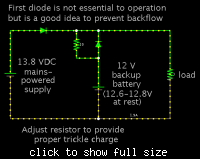
On the other hand if you can adjust the mains-powered supply to exactly 12.6 to 12.8 V, then the schematic below will work. No switches or relays are needed.

It has the benefit of providing power without interruption when a blackout hits.


The important thing is to prevent your 12V battery from being exposed to greater than 12.8 V. That is the resting voltage of a 12V lead-acid battery. (However if you believe your battery has a different resting voltage, then adjust your power supply to match.)
 

The important thing is to prevent your 12V battery from being exposed to greater than 12.8 V.
Can't agree on this point. Panasonic e.g. suggests 13.6 -13.8V for trickle charge and 14.5 - 14.9 V for time limited constant current/constant voltage charge.

12.8 V won't achieve full charging and may have a negative impact on battery life time.
 
The MOSFET-and-diodes-and-a-capacitor method works, but only just ; )
I used it to keep a device that needed 5v 2A powered up in the event of a power failure. It relies on the fact
that the capacitor has sufficient capacity while the MOSFET does it's switching.
There is a diode drop, mitigated a bit with schottky diodes. It was a quick hack, but so far is working ok.
I decided that since only 2A was required and a blackout was rare, I would live with a alkaline cost instead of
a lead-acid battery, so total cost was a couple of pounds compared to £20 or so for a small lead-acid battery from the
Maplin store (life is expensive in the UK : ).
 

FvM wrote:

Can't agree on this point. Panasonic e.g. suggests 13.6 -13.8V for trickle charge and 14.5 - 14.9 V for time limited constant current/constant voltage charge.

12.8 V won't achieve full charging and may have a negative impact on battery life time.

Fair enough. It all depends, of course, on how much trickle charge is healthy for the OP's battery. It would take some experimenting to find out.

I've seen advice both ways, as to trickle charging being a good idea, versus it being a bad idea. The risk is in the variations among inexpensive mains-powered chargers. The risk is increased when we're dealing with a small capacity battery.

Here is an alternate schematic:


thanks friend ,
BradtheRad, your idea is good but there is a problem, in this method battery and main power are parallel always and it is not good for battery and harmful for battery (is not it?) because perpetual current flow on battery, in my idea (Doc1.pdf) battery is cutting off.
but i must say a 10ohm series resister is need (that is correct).
can we use SCR or other power switches?

- - - Updated - - -

sky_123, thanks for your idea.
can you explain more or draw a simple schematic from your idea?
thank you.
 

IMHO the answer for sealed lead-acid battery backup is clear. You can either refer to the solutions used since decades or reinvent the wheel (optionally the square wheel, depending on your innovational strength).

I've briefly sketched in post #5 under which conditions a direct paralleling of battery, charger and load is possible. Referring to the comment of BradtheRad about "variations among inexpensive mains-powered chargers" I should clarify, that correct operation of the charger is presumed. An undervoltage load cut-off may be additionally required.

There may be special conditions that suggest to switch to cycle charge of lead-acid batteries although the load conditions would allow trickle charge. Elevated temperatures are a possible reason. But the charge (and charge keeping) algorithm has to be well considered to achieve good results.
 

thanks friend ,
BradtheRad, your idea is good but there is a problem, in this method battery and main power are parallel always and it is not good for battery and harmful for battery (is not it?) because perpetual current flow on battery, in my idea (Doc1.pdf) battery is cutting off.
but i must say a 10ohm series resister is need (that is correct).
can we use SCR or other power switches?

A reasonable case can be made for charging a battery and then disconnecting it from power.

I see your schematic indicates you will monitor its volt level with an ADC. So you can charge it whenever it needs it. This is fine.

You can probably use mosfet switching. (SCR's will be tricky because once they turn on, they stay on, until current drops below a certain level.)

I was not sure whether you needed uninterrupted power when power goes out, or whether it's okay for your circuit to lose power for a fraction of a second.

I believe there will be no harm to leave the battery connected, as long as the trickle current is not too great. However no one can be certain as to what to tell you is a safe continuous trickle current.

Sky_123's schematic shows a method that can be adapted to work for your situation.
 

I was not sure whether you needed uninterrupted power when power goes out, or whether it's okay for your circuit to lose power for a fraction of a second.
in my design it is not important (uninterrupted power or lose power for a fraction of a second) uninterrupted power is good i think.
I can use opamp for compare reference voltage with battery voltage instead ADC. (that is no problem)
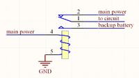
another question, can i use relay such as this picture for main switches in my diagram, connection main power and backup battery in lose power for a fraction mode?

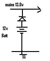
#10 post circuit is good for uninterrupted power but this circuit don't have any charger circuit, is it safe? i think we need a simple charger in this mode, with this idea we don't need any switches

and final my idea is in this picture , tell me your opinion
 
Last edited:

another question, can i use relay such as this picture for main switches in my diagram, connection main power and backup battery in lose power for a fraction mode?

Yes, it's a SPDT relay. It will work.
 
and your opinion about my final idea (final diagram)? is it good ? and don't have any problem?
 

Sealed Lead Acid battery voltage for :

Cycle charging : 2,45V per cell or 14,4V-15V
Float charging at 25C : 13,5V - 13,8V


Cycle charging is complete discharge and complete full recharge, on end stop charging or float charge voltage.

When Lead Acid is full and new, 24h resting after charging process OCV should be 12,72V-12,73V.

Also You can charge battery just with float charge voltage without problem.

Lead Acid request current control for charging.

Best data about your battery You can get from manufacturer datasheet.
 
hi friends

I design a circuit that need work with main power and backup battery, when main power disconnected i need backup battery supply my circuit automatically. my battery is 12V and main power is 13.8V and i need when return main power battery charging started and after raise it's voltage to 12V battery charge stop.
my battery is Sealed Lead Acid.

thank you.
Hi,
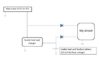
for your purpose I think this can help. for charging connect charging circuit to battery
3_1348048068.jpg

regards ani
 

Hi tpetar,
you can avoid D1 since the rectified DC is more than 12v
regards ani
 

Status
Not open for further replies.

Part and Inventory Search

Welcome to EDABoard.com

Sponsor

Back
Top