Continue to Site

Welcome to EDAboard.com

Welcome to our site! EDAboard.com is an international Electronics Discussion Forum focused on EDA software, circuits, schematics, books, theory, papers, asic, pld, 8051, DSP, Network, RF, Analog Design, PCB, Service Manuals... and a whole lot more! To participate you need to register. Registration is free. Click here to register now.

Need Help Line Following Robot

Status
Not open for further replies.

username134

Newbie level 4
Newbie level 4
Joined
Sep 13, 2012
Messages
5
Helped
0
Reputation
0
Reaction score
0
Trophy points
1,281
Activity points
1,315
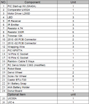
Im using ISIS 7.6 SP4 and MikroC. Im trying to simulate this robot. I would like to build this robot by buying each pieces since the kit is not available in our country. The pic in the kit SK40A should be PIC16F877A. I want to know what is J1,J3 and J100 in SK40A and the diode D2 is it LED? and some of the pins of the IC can't be seen in ISIS.

View attachment Code of line following.txt Line Following Schematic Diagram.pngSK40A.pngcomponent list.pngView attachment Description.pdf
https://www.cytron.com.my/usr_attachment/PR5_DD.pdf
 

in Proteus simulation POWER Pins are hidden mode.
click on the PIC16F877A,select edit properties , click hidden pins. you can see the hidden pins names.

VDD=VDD
VSS=VSS

you can change to
VDD=VCC
VSS=GND
 
The Js are just connectors
nothing significant
and yes the diode is actually an LED for determining if you have supply. I recommend you not use it since line followers are powered by batteries. You could always check VCC with a multimeter.
the pins are invisible because they are not important. they are vcc and gnd pins of chip.
 
j means jumper. The person who created the circuit has used jumper connectors in the design. They are 1 pin, 2 pin, and 5 pin connectors. you can use any similat connectors.

Yes, D2 is a led showing power supply state.
 
Thank you very much for your replies

- - - Updated - - -

Where should I connect those connectors? Could I just remove them?
 

Where should I connect those connectors? Could I just remove them?

You can just delete the "J" connectors, unless you plan to use connectors... then they might be ok to keep. Example, keep the two pin J3 connector so you can quickly connect/disconnect the battery pack to your microcontroller circuit (in case you need to remove power quickly because it running away, or just to unplug at the end of the night to keep the batteries from discharging).

If you plan to make your bot modular, using connectors to wire in the sensors is a good idea. You may be putting things off and on as you make adjustments and modifications, or if you burn out a sensor and have to replace it quickly. Just things to think about.
 

if you want run simulation with connector J1

click on connector J1 -> click edit properties button -> tick exclude from simulation check box [bottom, left side ].
 

Is there a software that can simulate the schematic? Im using proteus but it doesn't have IR
 

you can use a LDR - lamp combination .
Proteus component name TORCH_LDR
 

Status
Not open for further replies.

Similar threads

Part and Inventory Search

Welcome to EDABoard.com

Sponsor

Back
Top