Continue to Site

Welcome to EDAboard.com

Welcome to our site! EDAboard.com is an international Electronics Discussion Forum focused on EDA software, circuits, schematics, books, theory, papers, asic, pld, 8051, DSP, Network, RF, Analog Design, PCB, Service Manuals... and a whole lot more! To participate you need to register. Registration is free. Click here to register now.

I need Help (PIC16f84a) programming in assembly

Status
Not open for further replies.

ernestclydeachua

Junior Member level 1
Joined
Aug 5, 2012
Messages
15
Helped
0
Reputation
0
Reaction score
0
Trophy points
1,281
Activity points
1,380
relay driver pic16f84a

Im currently working in this project and searched and modified the circuit,

by using a spdt switch i can control a specific relay and LED
where

RB0 controls RB7 and RA0 ===>if RB0=0 then RB7 and RA0=0, else it will be 1 when RB0=1
RB1 controls RB6 and RA1
RB2 controls RB5 and RA2
RB3 controls RB4 and RA3
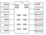


RELAY.jpg

i want to know the codes in Assembly language

- - - Updated - - -

i really want to know how to control each pins, i only know
movlw b'00000000'
movwf portb
 
Last edited:

the command btfss is quite helpfull for your case,but frankly i have no idea about spdt
to eplain btfss in more details assume you made porta as input and portb as an output
you could write

Code:
        btfss porta,0
        goto  i55
        bcf    portb,6
        goto  i56
i55    bsf   portb,7

this means if Ra0 of porta =1 then make Rb6=0 ( PORTB ) else make Rb7=1 (IN PORTB)
you have to read more in datasheet
to get the opposit use

btfsc
 
Last edited:
Code:
loop:
andlw PORTB_buffer, b'00001111'    ;clear bits 4-7
andlw PORTA_buffer, b'11110000'    ;clear bits 0-3

    btfss    PORTB,0
    bsf    PORTB_buffer,7
    bsf    PORTA_buffer,0
 
    btfss    PORTB,1
    bsf    PORTB_buffer,6
    bsf    PORTA_buffer,1
 
    btfss    PORTB,2
    bsf    PORTB_buffer,5
    bsf    PORTA_buffer,2
 
    btfss    PORTB,3
    bsf    PORTB_buffer,4
    bsf    PORTA_buffer,3

   movf PORTB_buffer, W      ;copy to working register
   movwf PORTB                  ;copy working register to PORTB

   movf PORTA_buffer, W      ;copy to working register
   movwf PORTA                  ;copy working register to PORTA

    goto    loop

can you check this out if this is right?
 

Hi,

You block diagram is clear, as far as it goes.

However a bit more info is needed to check it against your code, do the switches have a Pull Up or Pull Down Resistor.
Plus, do you have Mclre Pulled up and what Crystal are you using ?

Also the code you show is your main 'Loop' but do you have any other 'SetUp' code ? - it is better to show it all.

If you do not understand the above just say so an we can show whats needed to get your project working.
 

doesnt latch check the output ?
 

hi friend,I share with you a program that I use in my classes of MPLAB (assembler) with my students, there is like exploring a switch with a slight delay to prevent the rebound effect and then updates the outputs of PIC.
I'm sending the simulation (Proteus) and the MPLAB program.
Greetings friend and any questions my email is: jromeroa@upao.edu.pe
 

Attachments

  • app03.rar
    23.2 KB · Views: 92
Last edited:
Status
Not open for further replies.

Similar threads

Part and Inventory Search

Welcome to EDABoard.com

Sponsor

Back
Top