Continue to Site

Welcome to EDAboard.com

Welcome to our site! EDAboard.com is an international Electronics Discussion Forum focused on EDA software, circuits, schematics, books, theory, papers, asic, pld, 8051, DSP, Network, RF, Analog Design, PCB, Service Manuals... and a whole lot more! To participate you need to register. Registration is free. Click here to register now.

Very simple radio frequency amplifier

Status
Not open for further replies.

resurgence2012

Junior Member level 2
Joined
Apr 9, 2012
Messages
23
Helped
0
Reputation
0
Reaction score
0
Trophy points
1,281
Activity points
1,558
Here goes: I am trying to find a really simple radio frequency amPlifier circuit to Pick up a signal of about 100 MHz and display on an oscilloscope. I don't was to demodulate the signal just display the raw rf signal.

I have tried constructing a couple if pre-amps but don't seem to be able to display any signal on the scope. Any suggestions? I am really looking for the absolute simplest possible circuit. Cheers Peter
 

Hi - thanks - yes it is a pre-amp using a single

jfet http://www.techlib.com/files/fmpreamp.pdf

I don't seem to be able to get anything from it that I can display on my scope. Is it just that the signal is still too weak? Perhaps it needs another stage? I am still quite a novice. I don't reall know how big the signal coming from an rf pre-amp should be - as in the number of milivolts and amps - I am guessing it is quite small. When I tried probing my home made regenerative receiver, as soon as I get close to the real rf signal, the radio stops working, so I am guessing that the resistance of the scope is too low or the capacitance of the scope is coming into play.

Cheers

Peter
 

What exactly are you expecting to see?

If you use an untuned amplifier the output will be a combination of possibly thousands of signals, all with random amplitude, frequency and phase. The result will look like random noise unless one of the signals is much stronger than the rest, in which case it might be distinguishable from the background. Adding more amplification will not improve the situation, the signal is almost random prior to the amplifier so making it bigger will not help and indeed will increase the locally produced noise from it's own components.

If you want to see all the signals as peaks at different frequencies you need a spectrum analyzer, if you want to see just the 'raw' carrier of one station, you need to isolate it from the background using a tuned circuit.

Expect a signal of no more than a few mV, the current available from it will be a few uA at best.


Brian.
 
Thanks Brian. The main aim of what I am trying to do is to demonstrate the measurement of the sPeed of the radio waves. I intended using a small fm bug transmitter and then placing to receiving circuits a short distance apart. Feeding the received signals into two channels on the oscilloscope I would then hope to be able to read off the phase difference between the waves.

So yes, I need to use a tuned circuit. I was thinking about some kind of regenerative circuit without the FCC and quench followed by one or untuned stages. But then again, they could also be tuned. The idea of using 100 MHz is fairly abritary but it is based on the fact that my scope has a 50 Mz bandwidth and will comfortably, so it seems, display a 100 MHz sine wave. Cheers peter
 

It's a 'do-able' project but you need to take some things into account.

1. The 50MHz specification of the 'scope is the frequency at which the waveform display has dropped in amplitude by a certain amount compared to a lower frequency. Although 50MHz bandwidth maybe adequate, you are pushing your luck to see a 100MHz signal properly.

2. Not withstanding the above, the phase shift depends on the length of the wave so within reason, higher frequencies where the waves are shorter are more practical for the demonstration.

3. The 'FM' bug will not show any significant modulation on the signal you receive. The FM frequency shift will be insignificant so you could use any RF source to provide the signal. One with good frequency stability, such as a quartz crystal based ocillator will work best.

4. You might run into problems with regenerative receivers because to some extent the phase shift you see will depend on the bandwidth of the receiver and unless you can match the regeneration of the receivers you may get unpredictable results.

You haven't said who you are demonstating to but there are other ways of doing this which can be done on a table top rather than needing a wide separation between source and receiver. At 100MHz you need at least 3 metres to show one phase cycle, if you use much higher frequencies, maybe into the 10 GHz region, you can do it in a few cm although you would then be reliant on current measurement rather than viewing the waveform on an oscilloscope.

Brian.
 

Hi Brian, I teach science to students between 10 - 18 years. Really I am trying to extend and go beyond the run of the mill experiments that are offered. Earlier in the year the students used a microwave oven and were able to make a very crude measurement of the distance between 'hotspots' produced by standing waves.

I wanted to see if there was a simple way of making a much more accurate measurement of the speed of EM waves. I have been toying with this for months. Earlier in the year I was trying to see if I could rig up a mechanical beam chopper to reproduce Fizeau's experiment. I also tried the rotating mirror method, but without expensive optics and someone to show exactly how it is done I had no success.

That's when I started wondering about using radio waves.

I am still working on another method using IR diodes. Actually this morning I tried just using a resistor in series with an IR detector and putting 30 volts reverse bias. Using a really cheap little remote control, I was amazed at how sensitive the thing was. I was point the remote in the opposite direction, at the floor, at the ceiling, and no matter what I could see the trace on the scope jump every time I switched it on. Only when I literally covered it completely with my hand did it stop responding.

I have a circuit diagram using an avalanche transistor (I have the transistor) to make about 5 nano second pulses of the driving diode. The only thing I need to do is find out what the response rise time of the detector actually is and whether it is fast enough.

Why all the bother? Basically I am teaching myself and trying to expand my own limited knowledge. This particular problem seems to be quite fruitful in terms of leading down many new avenues.

Your suggestions are all welcones greatly. Cheers Peter
 
Last edited:

One classic experiment you can try is very simple but the parts can be tricky to find:

You need a Gunn diode oscillator and mixer as used in automatic door opening equipment. If you can find one second hand they cost pennies, I'm in the UK and they can be found at electronics fairs and junk sales for around £3 ($5 US), often with the seller having no idea what they are. They look like a metal block with two insulated pins and a rectangular waveguide slot on one end. When about 9V is put on the pin furthest away from the slot, they start to produce microwaves at around 10.7GHZ. The second pin is the mixer output, basically a connection to a diode mounted a few mm inside the slot.

The trick is to measure the current from the mxer diode (the metal case is the ground connection), it will be a few 10s's of uA. When an object is moved in close proximity tio the slot, the current will vary, this is what the door opener uses to know somebody is aproching. Now place a flat reflector in front of the waveguide and move it back and forth. Part of the output power is internally coupled to the mixer, part comes from reflections back into the slot from outside. As the reflector is moved, the phase of the reflected waves reaching the mixer will change but the fixed path inside the unit will remain constant so the waves will interfere constructively or destructively depending on the reflector distance. The nice thing about this experiment is it is compact and by measuring the distance between peak and trough curents, the wavelength and therefore frequency can be calculated.

Brian.
 

33.gif

37.gif


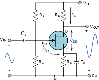
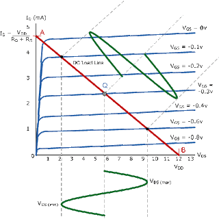
hi resurgence2012 im giving a reference images for fet amplifier and u can get more information about amplifier design
Click Here For Amplifier Tutorial
 

Status
Not open for further replies.

Similar threads

Part and Inventory Search

Welcome to EDABoard.com

Sponsor

Back
Top