Continue to Site

Welcome to EDAboard.com

Welcome to our site! EDAboard.com is an international Electronics Discussion Forum focused on EDA software, circuits, schematics, books, theory, papers, asic, pld, 8051, DSP, Network, RF, Analog Design, PCB, Service Manuals... and a whole lot more! To participate you need to register. Registration is free. Click here to register now.

Why the separation is twice times of the trace width? [Transferred from RF Forum]

Status
Not open for further replies.

tony_lth

Advanced Member level 5
Joined
Jul 28, 2010
Messages
2,098
Helped
377
Reputation
756
Reaction score
368
Trophy points
1,363
Location
Beijing
Activity points
12,727
Why the separation is twice times of the trace width?
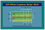
For difference offset Coplanar strips,
If the trace width W1 is 60um.
Option1: S1=120um, D1=120um, then get Zdiff=90.99 ohms.
Option2: S1=300um, D1=300um, then get Zdiff=98.93 ohms.
Someone said that S1 and D1 should better be twice times of W1. So he denied option2 because of not 100 ohms diff impedance.
I think option2 is feasible, who can give comments on that? Attached Thumbnails
 

Attachments

  • Diff_Coplanar.png
    Diff_Coplanar.png
    38 KB · Views: 97

I think it's some kind of "thumb rule" to reduce crosstalk between the lines
 
Hi, shaiko,

Thanks for the reply. Can you explain detaily?
 

Separation of twice trace width refers to relatively low impedance line as individual microstrips or striplines. It is the amount of coupling between lines. Most differential lines on a PCB board are really independent single ended lines driven at ends from a balanced source. For example, to make a 100 ohm balanced line there is two 50 single ended lines to ground plane. It is practically impossible to make these close enough (obeying PCB ,minimum line width and line separation rules) to get much odd mode coupling between lines.

Most of fields are confined between the individual runner and ground plane below runner.

You obviously need to make the two single ended lines the same length from source to load but keeping them together is relatively unimportant from an impedance perspective since they have very little cross coupling. You may gain some common mode noise reduction keeping the lines together.
 
Last edited:
Hi, RCinFLA,

Thanks for your reply.

I forgot one thing. The signal is diff RF signal, such as 1900M Rx diff signal from antenna to modem.

At this time, I think trace impedance is more important than trace length for the diff rx signal. Right?

From the crosstalk point, more separation is better than twice times, right?

Thank you very much.
 

Status
Not open for further replies.

Part and Inventory Search

Welcome to EDABoard.com

Sponsor

Back
Top