Continue to Site

Welcome to EDAboard.com

Welcome to our site! EDAboard.com is an international Electronics Discussion Forum focused on EDA software, circuits, schematics, books, theory, papers, asic, pld, 8051, DSP, Network, RF, Analog Design, PCB, Service Manuals... and a whole lot more! To participate you need to register. Registration is free. Click here to register now.

Current limiting 12v, 1.8a

Status
Not open for further replies.

xmen33

Newbie level 5
Newbie level 5
Joined
Aug 28, 2011
Messages
10
Helped
0
Reputation
0
Reaction score
0
Trophy points
1,281
Activity points
1,359
Hi

I went a circuit diagram to limit the current by 1.8A with 12v

other Question : if i have a device , it draw 12v, 3.2A
by using this circuit it will draw 12v,1.8a ?
 

Dear xmen
Hi
I think you forgot to attach your schematic ! what kind of current limiter ? DC ? AC ? how much is the voltage range ?
Best Wishes
Goldsmith
 
Dear xmen
Hi
I think you forgot to attach your schematic ! what kind of current limiter ? DC ? AC ? how much is the voltage range ?
Best Wishes
Goldsmith

I Think that u didn't get what i say ,
First i went to circuit diagram to limit the current by 1.8A with 12v
second i went to know " if i have a device , it draw 12v, 3.2A
by using this circuit it will draw 12v,1.8a ? "
 

PWM.jpg

you can make a PWM oscillator which acts is not an active device but It will restrict the current.
 
you can make a PWM oscillator which acts is not an active device but It will restrict the current.
What? Did you post in the wrong thread by mistake? Why did you put a copy of Shaq's buffer circuit next to an oscillator circuit?
 
  • Like
Reactions: tpetar

    tpetar

    Points: 2
    Helpful Answer Positive Rating
Oops lol i had the other circuit open on my other screen. Anyway the circuit in the left hand side is a PWM oscillator. It will change the duty cycle and it would average the current out to 1.8A if necessary
 

Dear karthick
Hi
The circuit that you have suggested seems pretty good . i didn't know that we can create PWM with a simple not gate . thank you for that . but i have added another not gate in it's out put , thus the out put wave became sharper .
See below , please :
PWM.JPG
PWM shape.JPG

But i'm i was wondering that how can i set this circuit to achieve D.C around 0 up to 100 percent without any variation in frequency . your circuit has not any variation in frequency but it's D.C is restricted to the special range .

Best Regards
Goldsmith

I Think that u didn't get what i say ,
First i went to circuit diagram to limit the current by 1.8A with 12v
second i went to know " if i have a device , it draw 12v, 3.2A
by using this circuit it will draw 12v,1.8a ? "


No i understood what you mean , but you simply want to limit the current . but current of what kind of circuit ? it is important . why you didn't attach any schematic ?
Best Wishes
Goldsmith
 
@xmen33
Have you wanted to write "went" or "want"?????? Your question doesnot seems to be clear....
 

I have a stepper motor 1.8A for phase with 2.1 ohm ( from center tab ) and 6 wire #sanyo denki 103h6703-0341.
I using a tip122 with 56 ohm at it's base , add a diode between collector and power supply and i will use 12v power supply to run the driver.
so i want ( not went :grin: ) to limit the current to protect the motor from high current.
i figure a way to calculate the limiter resistance ( don't know if it right )

First :
Resistance that i will put after power supply = ( (12V / 1.8A) - 2.1 ohm ) ~ 4.5 ohm
power = 1.8 * 12 =21.6
so resistance = 4.5 ohm 22 watt

Second :
1.8A is for one phase so what about when the motor run 2 phase
1100,0110,0011,1001
so i think that there are some thing wrong :|
 

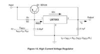
Why dont you increase the base resistance to a required value so that you get an optimum current for your motor. Or else you can use the following circuit....


Use LM7812 for a constant 12 volt and transistor BD536 (or equivalent) will help to increase current upto 1.8 amp.
(LM7812 has current limit of upto 1 amp)
 

First :
Tip122 need VBE (on) = 2.5v and Ib = 120 mA, so i need 20ohm to turn on this transistor.
Second :
I think that if i used lm78XX ,i it will be heat so much because the motor will receive 1.8 amp and the volt must drop so make the motor stable.
so the resistance will be better then lm78xx because it can handle high watt.

- - - Updated - - -

other thing:
the equation is : Resistance that i will put after power supply = ( (12V / (1.8A *2 )) - (2.1//2.1) ohm ) ~ 2.3 ohm
power = 1.8 * 2 * 12 = 43.2 watt
so resistance = 2.3 ohm 43.2 watt
right ?
 

But i'm i was wondering that how can i set this circuit to achieve D.C around 0 up to 100 percent without any variation in frequency . your circuit has not any variation in frequency but it's D.C is restricted to the special range .

Hi goldsmith,

i have used this circuit several times and I havent noticed any limitations in the D.C. I am sure by varying the pot you can get something close to 0 and something nearly 100. So not sure what you mean.

Also xmen33 if you are after current control why dont you just use a power transistor something like thisstepper.jpg

it should work just fine. just choose the right transistors ( watch out for Ice ratings!) if thats not sufficient try to parallel the 2 transistors together.

thats an interesting one Genovator never used that circuit before. I shall look into it

Cheers
K
 

Well, in the circuit I have shown, the voltage will not drop. So I think it is of no use to you. But it can easily withstand the current of 1.8A. Because LM7812 will be carrying 0.8Amp and the NPN transistor shown l carry the rest of 1.0Amp. Just a small calculations of resistors will do.

And as per your resistance equation, there will be a high power dissipation. Why to loose such energy?
 

Hi again karthick
What are those inductors in your circuit ? and about what i have seen , i have simulated your circuit in Ps pice , and it's duty cycle couldn't change from zero up to 100 . can you show me your simulations , please ? perhaps my simulation was not correct ?
Regards
Goldsmith
 
Last edited:

Hi Genovator

the resistance of motor is 2.1 ohm and will be 1.05 ohm ( and the current the motor need will be 1.8A * 2 ) when the motor active 2 phase .
and my power supply will output 12v ( cant change )
so i cant run the motor with 12v because the current will increase so the motor will burn.
with your circuit , the output should be 12v , 1A ( as datasheet of LM7812 ) so the volt must drop to balance with 1.05ohm ( the resistance of motor constant ) and the LM7812 will get hot very fast.
Am I correct ?
 

Yes and no....

LM7812 will draw half of the current. So it will not become hot. The other half will be drawn by the transistor BD536. (Check my diagram). I think the motor will draw that much of current which is required by it. It will be working on its full efficiency. It can never "get" current, it will just draw that amount. TIP122 or any other device just "allows" the motor to draw that current.
 

Hi again karthick
What are those inductors in your circuit ? and about what i have seen , i have simulated your circuit in Ps pice , and it's duty cycle couldn't change from zero up to 100 . can you show me your simulations , please ? perhaps my simulation was not correct ?
Regards
Goldsmith

I dont have the simulation with me. I tried the simulation yesterday and my windows crashed ! Anyway I have made it up and checked it on the scope a few times. But I might try and build it up again and check. I will let you know soon.

Cheers
K
 

But i'm i was wondering that how can i set this circuit to achieve D.C around 0 up to 100 percent without any variation in frequency . your circuit has not any variation in frequency but it's D.C is restricted to the special range .
Hi
I think it may work better with the potentiometer connected like this:


Hi daer godfreyl
Thanks as i saw the original post of karthick i knew it but for simplifications i have used two resistors in Pspice , just for simulations . ( i don't know how to use potentiometer in pspice ( because when simulations is run , i can't change it and see the result .

I dont have the simulation with me. I tried the simulation yesterday and my windows crashed ! Anyway I have made it up and checked it on the scope a few times. But I might try and build it up again and check. I will let you know soon.


Hi dear karthick
Thanks , i will wait for your result .

Best Regards
Goldsmith
 

Status
Not open for further replies.

Similar threads

Part and Inventory Search

Welcome to EDABoard.com

Sponsor

Back
Top