Continue to Site

Welcome to EDAboard.com

Welcome to our site! EDAboard.com is an international Electronics Discussion Forum focused on EDA software, circuits, schematics, books, theory, papers, asic, pld, 8051, DSP, Network, RF, Analog Design, PCB, Service Manuals... and a whole lot more! To participate you need to register. Registration is free. Click here to register now.

1000 watt pure sine wave inverter

Status
Not open for further replies.

reynier1223

Junior Member level 2
Joined
Jun 3, 2012
Messages
24
Helped
0
Reputation
0
Reaction score
0
Trophy points
1,281
Activity points
1,504
good day esteemed members of the forum

pls can someone help me with a circuit diagram for a 1000 watt pure sin wave inverter pls
thankyou in advance
 

Its hard to find anywhere. These circuits are highly complex and very expensive to build. Although, I found this simple one. Hope it helps you....
**broken link removed**

[The rectifier bridge is wrongly plotted]
 

    Santorsix

    Points: 2
    Helpful Answer Positive Rating
thanx genovator that circuit will help, i hope.
i am kinda new to the electronics world, so could u help me out with a parts list, if possible pls.
i see that most of the parts on the diagam does have part name, but some dont. if u could help me with that pls.
kind regards
 

For last few days I m trying to resolve about how I should help you. Creating a sine wave is not a easy matter.
The link I posted in my last post is not so convenient. It will be hard to explain.
.
Well, there are lot of ways to create sine waves. But it is upto you which way you can follow- creating a pulse width modulation waves or simply a square wave and pass it with a low pass filter. Or creating a virtual sine wave with the help of a microcontroller, passing through a couple of power mosfet and then boosted with a transformer.
By the way, making a sine wave inverter is much costlier, risky, and of full of headache. If you wish to make it at home, we can proceed.
---------------------------
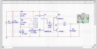
If you use a low pass filter in square wave, the below circuit can help.....


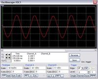
Its waveform is..


I remade this circuit few months ago. It has a drawback that 1H inductor and 5uF capacitors are of larger value. You can use some lower values also, but the output will not be a PURE sine.
------------------
And if you use a microcontroller, then refer to the pdf below...
 

Attachments

  • sine inverter.PDF
    273.6 KB · Views: 712
thank you so much Genovator for the responce.
i do want to build the inverter at home.
i relize to build a sin wave inverter is more costly. I stay in south africa and we only use sin here, so i dont have any choice.
i think the one with the micro controler is the best, as it will give the purest sin wave. I realize the micro controler has to be programed, i unfortunatly dont know how to do that. pls can u explain to me how to program it.
i have read on the internet about modifide square wave that is as good as sin wave, do u know anything about it.
Thank u again very much, hope to hear from u soon.
have a great day.
 

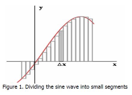
Modified square waves are as same as you seen in the microcontroller project which I uploaded. These are a 'step increment and decrement' of small fragments of square waves 'in a single cycle', which as a whole, represents a virtual sine wave. Higher number of fragments in a cycle helps to make a good sine wave with a small unit of low pass filter.

59_1340643410.jpg


Well, if you choose to use a microcontroller then you have to study many new things first. Do some google search on uC(microcontrollers) specially on AT89S series, how they work, how to program them, how to build software to make them work, choosing crystal oscillators, etc. It also brings an additional expenses to design a programmer circuit to program the uC.
I sent an e-mail to the owner of that uC inverter project. Let's see if they reply me.

You download some circuit simulation softwares to make the circuit virtually in your PC. Check whether it works or not. If you want to start, make the project in PC first.
 

Thanx for the explanation Genovator, so one can evectivly simulate a sin wave in that way.
I will search for the uC info on the net, and look forward to hear about the project from u if the owner emails u back.
About the lm555 circuit, does that give a good sin wave, it seems to be easier to build, witch one would u say is the beter one to try.
I also want to find out from u, if i want to u upgrade the inverter to say a 2Kwatt inverter, can i do that by adding more power transistors in parralell to the circuit. And i want to see to use a 24 v DC supply, what chages would i have to make to adjive this.
Thank you for all your help.
hope to hear from u soon.
Thanx, have a great day
 

LM555 will never give sine waves. It gives a pure 'square' wave. We have to filter it with capacitor and inductor.

I would recommend to make inverter on LM555 timer IC. Its easy, compact, low cost, and will be good to start first....

You can upgrade your inverter wattage by considering some points:
1. You need a high wattage transformer
2. Source voltage should be more than 12 V (say 24 V or 48 V) by adding 2 or more batteries in series.
3. Wires used in input and output load should have high voltage capacity.
4. Inductor is in series, therefor it should have rating of more than 10 amp.
etc.

You choose one.....
 

I will try the LM555 first thanx Genovator
Maybe a silly question, but can one make the sin wave more pure sin with more caps and inductors? or is it posible to make it more pure?
To upgrade the inverter, all those points u named is true, but shouldent the circuit also be upgraded? I saw on a other circuit diagram when i was searching for circuit diagrams that it said to increase the power rating of the inverter, u shouls add more power transistors in parrall.
Or could it only be for that diagram?
Have a great day.
Thank you
 

Hello reynier,i wont advice you to try that inverter using NE555 because you will end up setting fire on your project, their are many simple inverter circute that uses center tap transformer just search for one and try it .
 
Yes,i know about this circuit diagram of this inverter it works fine you can start with it.
 

I Genovator and Kabiru, thew circuit u posted looks nice, but is it a sin wave inverter?
Genovator, about the lm555 circuit, can one make it a more pure sine by adding more caps and inductors? and increase the power by adding more power transistors like in the post u gave now.
Have a nice day
hope to hear from u soon
enjoy
 

The circuit is not pure sine wave is just modified sine wave,if you need pure sine then you need to generate pwm signal .
 

Yes... for kabiru..

And about LM555, adding more caps and inductors doesnot mean it will be a pure sine wave. It just helps to change the waveform from square to sine. Adding more than required will cause a drastic change in the waveform.

Yes, adding transistors in that way can increase its power dissipation limit. Transistor 3N3055 has a power dissipation rating of 115 W. That is, adding two transistors in the opposite side of the coil as shown will increase its power capacity to another 100 W. I like transistor 2N5303. Its power dissipation rating is 200 W.
 

Thankyou for all your help Genovator i realy apriciate it.
I am first going to build the LM555 inverter, for my first try. Will keep u updated with my progress.
For Kabiru, do u have such a pwm circuit diagram for me pls, ultimatly i do wish to build an inverter with a pure sin wave.
Thankyou again for all the help
Enjoy the day
Thanx
 

All the best to you.... But remember, this is your first time so better design the inverter for only 100 Watt. Power is not a big factor. You can increase it in future by making some changes.

Use transistors like:
NPN 2N3055
PNP MJ2955


Best of luck....
 

you can only make square wave inverter using 555 IC and power transistors. you have to make sine weighted pulses using a microcontroller or comparing a standard sine wave with triangular wave and create sine weighted pulses. after that u can use power transistors to output it to a power transformer to the required voltage.
regards ani
 

Good day Genovator
Hope you are doing well
I have finaly found a 1H inductor, but the largest amprage rate one I could find is a 250 mA inductor.
I want to know from you if you perhaps know the max power output I can make my inverter with that inductor.
I dont want to make the output to large and in so doing burn out the inductor.
Hope to hear from u soon
Thankyou very much.
Have a wonderfull day.

- - - Updated - - -

Good day Genovator
Hope you are doing well
I have finaly found a 1H inductor, but the largest amprage rate one I could find is a 250 mA inductor.
I want to know from you if you perhaps know the max power output I can make my inverter with that inductor.
I dont want to make the output to large and in so doing burn out the inductor.
Hope to hear from u soon
Thankyou very much.
Have a wonderfull day.
 

If its amperage rating is 250mA, then of course it cant draw more than that current. Its power rating will be 230x0.250=57.5 or around 50Watt or less. This inductor cannot be used.

This is why 'kabiru' posted that 'you will set fire in the circuit'. This circuit is only possible to make, but not acceptable. its just easy.

Try some lower rating inductors with high amperage in series.
 

Status
Not open for further replies.

Part and Inventory Search

Welcome to EDABoard.com

Sponsor

Back
Top