Continue to Site

Welcome to EDAboard.com

Welcome to our site! EDAboard.com is an international Electronics Discussion Forum focused on EDA software, circuits, schematics, books, theory, papers, asic, pld, 8051, DSP, Network, RF, Analog Design, PCB, Service Manuals... and a whole lot more! To participate you need to register. Registration is free. Click here to register now.

[SOLVED] basic current measurement value through LED

Status
Not open for further replies.

kdg007

Full Member level 3
Full Member level 3
Joined
Jan 6, 2012
Messages
162
Helped
1
Reputation
2
Reaction score
1
Trophy points
1,298
Activity points
2,420
lled.jpg
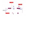
i designed a basic circuit as in the picture.When i given the voltage from voltage regulator.The measured current through LED is same as the simulation = 12.7mA. but when i connected to the Frequency generator(10kHz with DC OFFSET of 5V),
the current through the LED is double the value ??why is it ??
lled.jpg
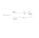
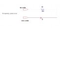
i checked without the LED ,the current through the resistor in both cases shows 16mA...
lled.jpg
lled.jpg

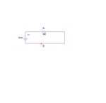
why is it that if i keep the LED the current value doubled with the frequency generator ???
-
i tried out with the white LED (Vf of 3.3 )...with the voltage regulator(5v) , the current through LED is 18 mA with 100 ohm resistor.
but its with the frequency generator ,the current through the LED is 40mA with 100ohm resistor.am i missing something ? i want to understand this...
 
Last edited:

View attachment 75975
i designed a basic circuit as in the picture.When i given the voltage from voltage regulator.The measured current through LED is same as the simulation = 12.7mA. but when i connected to the Frequency generator(10kHz with DC OFFSET of 5V),
the current through the LED is double the value ??why is it ??
View attachment 75978
i checked without the LED ,the current through the resistor in both cases shows 16mA...
View attachment 75976
View attachment 75977

why is it that if i keep the LED the current value doubled with the frequency generator ???
-
i tried out with the white LED (Vf of 3.3 )...with the voltage regulator(5v) , the current through LED is 18 mA with 100 ohm resistor.
but its with the frequency generator ,the current through the LED is 40mA with 100ohm resistor.am i missing something ? i want to understand this...


I am guessing that you have this problem because of the DC offset of your signal.
You have 5 V of DC as offset plus your 10Khz signal.
If you add the 5 VDC plus the 10khz with ans RMS value of 3.53., you get 8.53 V.
If you divide that by your 300 Ohm resistor, you get your double value of current, 28.43 mA.

The DC offset is the one pushing the current up.
If you only apply AC with no DC offset, you should get the same result as your DC test, probably less because it's RMS.

I could be wrong about all this, but it all points in that direction.
 
  • Like
Reactions: kdg007

    kdg007

    Points: 2
    Helpful Answer Positive Rating
RMS value of 3.53?? how do u cameup with 3.53????
 

I am guessing that your Vp of your frequency is 5 V. So, 5/√2=3.53 V. That's how I came up with those numbers.....
 
There's no real information about the "frequency generator" output settings. Thus all guesses are void.
 
  • Like
Reactions: kdg007

    kdg007

    Points: 2
    Helpful Answer Positive Rating
why square r0ot 2 ?
-

information of freq generator :

frequency - 10khz
trig level - CONT
DC offset - 5V
LIN
Pulse width variable - 10ns
transit time - 7ns
output attn(db) - 0

-

anything i am missing ?
-
i checked the Vf for the white LED... it is showing 3.3v (with 100ohm resistor in series with 5v from voltage regulator.@17mA across it).
the same conditions but with frequency generator ,it is showing -7.38v Vf (with dc offset of -5.59v @ 17mA )
 
Last edited:

anything i am missing ?
AC output voltage, waveform.

The basic point is that with a nonlinear load like a LED, the DC current is no longer set by the average voltage (DC offset) when an considerable AC is superimposed. With a pure resistive load, it still is.
 

AC output voltage, waveform.
My point exactly.
My guess was only based on his readings.
I agree with you that in analysis you don't make any asumptions.
I was getting an estimate based on what it was presented.
Without the Vp of the waveform, nothing can be determined completely.
 

You do not say how you are measuring the current.

Is it with a cheap Multimeter?

If so, is the meter set to DC or AC range?

A cheap multimeter may be designed to give accurate readings only for pure DC on DC range, and pure sine wave on AC range.

A cheap multimeter may be designed for mains frequencies, rather than the 10KHz that you are using.

I think I would measure the voltage across the resistor with a scope if I wanted a true picture of what is going on.
 

photo.JPG

the current through LED is 48mA with DC offset of 5V...(LED forward voltage is 3.34V)
-
the top waveform is from frequency generator and the bottom one is from the LED-5v/div - )
 

In case of a square wave, the calculation of the average current is easy. You determine the LED current for both high and low level of the input signal and calculate the average.
 
  • Like
Reactions: kdg007

    kdg007

    Points: 2
    Helpful Answer Positive Rating
for high level is 48mA .... how to get for the low level ?
 

for high level is 48mA ....
The low level current will be surely zero. But how did you determine the 48 mA value? If the previously told average current valiue of 40 mA is correct, the high level would be 80 mA.
 
  • Like
Reactions: kdg007

    kdg007

    Points: 2
    Helpful Answer Positive Rating
Give some websites to learn the basics of embedded system which is very user friendly and let me know about the forums too. i am basically a biotech student.
 
  • Like
Reactions: kdg007

    kdg007

    Points: 2
    Helpful Answer Positive Rating
Status
Not open for further replies.

Part and Inventory Search

Welcome to EDABoard.com

Sponsor

Back
Top