Continue to Site

Welcome to EDAboard.com

Welcome to our site! EDAboard.com is an international Electronics Discussion Forum focused on EDA software, circuits, schematics, books, theory, papers, asic, pld, 8051, DSP, Network, RF, Analog Design, PCB, Service Manuals... and a whole lot more! To participate you need to register. Registration is free. Click here to register now.

pic16f887 in circuit programming?

Status
Not open for further replies.

Sajjadkhan

Full Member level 5
Full Member level 5
Joined
Sep 25, 2010
Messages
307
Helped
17
Reputation
34
Reaction score
16
Trophy points
1,298
Location
Rawalpindi,Pakistan
Activity points
4,199
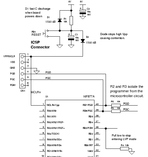
Hi, i am willing to use tqfp-44 package instead of dip 40. i going to use pickit3(first time), i have used different programmer, the one with dip socket. any one kind enough to tell me how this chip is going to be progeammed, since i can not desolder it for programming. Also which pins of this pic would be used in programming and should i use them in my circuit or should i left them souly for programming purpose?
 

Hi,

First thing, download and read the Pickt3 User manual. https://ww1.microchip.com/downloads/en/DeviceDoc/51795B.pdf
It details how to connect the Pk3 to a target board.

For the 887 you only have one set of programming pins MCLRE, PGC, PGD plus Vss and Vdd.

Dependant on the particular function, it may be possible to also use those three programming pins for the user circuit, though I always find it best to leave them totally free for programming and Debugging with is a very useful tool.
 
OK i have read the manual but sill i am confused about 2 things.

1. should i connect the pickit3 Vdd to target boad vdd or should i left it open? and if connected then will pickit3 be damaged if i turn on the target board via external power supply? i usually supply 5.12 Vdd to pic for the adc step size.

2. kindly explain the function of LVP i know pikit3 can program the pic when LVP is disabled, but does it mean that if i dont use PIckit3 Vdd then as an alternate i can use LVP to program it?

Hi,

No, it will not harm the PK3 if the target Vdd is connected at 3v or 5v, give or take a couple of points; 5.2v fine.
The Pk3 has inbuilt diodes to protect itself.

You do not need to connect VDD to the target board if it has its own power, but VSS, 0v must be connected

LVP is programming memory without taking Mlcre/VPP to 12v, not generally used. ( without getting into a complicated debate)
Normally you just use the standard programming method using VPP.

I only use the PK2 but the software and hardware are well proteced against wrong connections; a message will soon pop up to say things are not right.
 
thank you so much .ok one more thing. i need to use icspdat and icspclk as gernal purpose output pins. will my pic still be programmed? these pins are driving 2 pins of uln2003. or in gernal what restriction do i have to use these pins as input/output. i read somewhere that dont connect complicated circuits with it like lcd or so sensitive sensor but if there being use to drive like transistors than its ok.

- - - Updated - - -

people prefer pickit2 more than pickit3 why is that?
 

i need to use icspdat and icspclk as gernal purpose output pins. will my pic still be programmed?

Yes, you must disable In Circuit Debugging as well as Low Voltage Programming by the appropriate Configuration Register settings.

The application of the proper Programming Voltage Vpp on MCLR pin will ensure the device is in High Voltage Programming (HVP) mode, regardless of the Configuration Register settings.

these pins are driving 2 pins of uln2003. or in gernal what restriction do i have to use these pins as input/output. i read somewhere that dont connect complicated circuits with it like lcd or so sensitive sensor but if there being use to drive like transistors than its ok.

Both RB6/PGC and RB7/PGD pins are driven an logic levels equal to Vdd at the time of programming, therefore they are not subject to the relatively high voltage of Vpp to which is only applied to MCLR pin. However, you should ensure that any attached devices to these pins to not interfere with either the Clock (PGC) or Data (PGD) during the programming phase. Depending on the attached device this can range from a simple resistor to a jumper to isolate the pin during programming.

There have been some reports that it maybe necessary to pull down the RB3/PGM as well as disable the LVP within the Configuration Register settings, depending to the device and the programmer being used.


Configuration Register Bitmasks pic16f877.h

#ifndef _HTC_H_
#warning Header file pic16f877.h included directly. Use #include <htc.h> instead.
#endif

/* header file for the MICROCHIP PIC microcontroller
* 16F877
*/


#ifndef __PIC16F877_H
#define __PIC16F877_H

//
// Configuration mask definitions
//


// Config Register: CONFIG
#define CONFIG 0x2007
// Oscillator Selection bits
// RC oscillator
#define FOSC_EXTRC 0xFFFF
// HS oscillator
#define FOSC_HS 0xFFFE
// XT oscillator
#define FOSC_XT 0xFFFD
// LP oscillator
#define FOSC_LP 0xFFFC
// Watchdog Timer Enable bit
// WDT enabled
#define WDTE_ON 0xFFFF
// WDT disabled
#define WDTE_OFF 0xFFFB
// Power-up Timer Enable bit
// PWRT disabled
#define PWRTE_OFF 0xFFFF
// PWRT enabled
#define PWRTE_ON 0xFFF7
// FLASH Program Memory Code Protection bits
// Code protection off
#define CP_OFF 0xFFFF
// 1F00h to 1FFFh code protected
#define CP_UPPER_256 0xEFEF
// 1000h to 1FFFh code protected
#define CP_HALF 0xDFDF
// 0000h to 1FFFh code protected
#define CP_All 0xCFCF
// Brown-out Reset Enable bit
// BOR enabled
#define BOREN_ON 0xFFFF
// BOR disabled
#define BOREN_OFF 0xFFBF
// Low Voltage In-Circuit Serial Programming Enable bit
// RB3/PGM pin has PGM function; low-voltage programming enabled
#define LVP_ON 0xFFFF
// RB3 is digital I/O, HV on MCLR must be used for programming
#define LVP_OFF 0xFF7F

// Data EE Memory Code Protection
// Code Protection off
#define CPD_OFF 0xFFFF
// Data EEPROM memory code-protected
#define CPD_ON 0xFEFF
// FLASH Program Memory Write Enable
// Unprotected program memory may be written to by EECON control
#define WRT_ON 0xFFFF
// Unprotected program memory may not be written to by EECON control
#define WRT_OFF 0xFDFF
// In-Circuit Debugger Mode bit
// In-Circuit Debugger disabled, RB6 and RB7 are general purpose I/O pins
#define DEBUG_OFF 0xFFFF

// In-Circuit Debugger enabled, RB6 and RB7 are dedicated to the debugger
#define DEBUG_ON 0xF7FF

If you are using MikroC that Configuration Register bits must be set within "Edit Project" Dialog Box:


people prefer pickit2 more than pickit3 why is that?

While I only use the ICD2/3 and Real ICE, I would imagine price and the availability of numerous PICkit2 clones and variant designs.

There are numerous PICkit2 clones available on the market and an equal number of PICkit2 compatible designs for the DIYer.


Hope the info helps,

BigDog
 

Hi,

The PK2 proved such a success because it was a good price and most of the time it worked without problems, it also had a good collection of useful utility programs like USART Tool and Logic Analyzer.

Everyone expected the PK3 to be the same but better, sadly it seems, from what I read, that it falls well short of that.
The original version was said to be very poor software wise, apart from the fact it could program all the new devices, it did not seem to have any real advantage over the Pk2, particularly as it cost almost twice as much.

Today the software has been improved, the price reduced a bit, depending where you are, and many folk say they have no trouble with it.
However, get to know this forum in case you have any questions /problems/ updates https://www.microchip.com/forums/tt.aspx?forumid=15

If you use pgd/pgc for output pins you will not be able to use the PK3 dubgger function.
Having read the PK3 user guide there is no reference to using those pins for outputs and ICSP.
On the PK2 they do show the ICSP direct connections with a serial resistor, 470r or 1k, being taken off those pins to other circuitry.

I do not know if that resistor method would work with the PK3 ? If no one else here can help then try the Microchip forum.

AH, Big Dog has just answered the point.
 

Status
Not open for further replies.

Similar threads

Part and Inventory Search

Welcome to EDABoard.com

Sponsor

Back
Top