Continue to Site

Welcome to EDAboard.com

Welcome to our site! EDAboard.com is an international Electronics Discussion Forum focused on EDA software, circuits, schematics, books, theory, papers, asic, pld, 8051, DSP, Network, RF, Analog Design, PCB, Service Manuals... and a whole lot more! To participate you need to register. Registration is free. Click here to register now.

my pickit2 clone comes this message

Status
Not open for further replies.

PA3040

Advanced Member level 3
Joined
Aug 1, 2011
Messages
883
Helped
43
Reputation
88
Reaction score
43
Trophy points
1,308
Activity points
6,936
Dear All
most of times my pickit2 clone comes this message when I (blank check)
then I used my serial programmer and erased using it and re erased using PICkit2 clone then it will be success

please advice

pickit2.JPG

pickit2se.JPG
 
Last edited:

Dear All
most of times my pickit2 clone comes this message when I (blank check)
then I used my serial programmer and erased using it and re erased using PICkit2 clone then it will be success

please advice

Hi,

Normally you do not need to Blank check or Erase a chip, when you Write it automatically does all those functions for you.

Just load in your new program code and press Write, whatever was on the chip will be Erased and the new code programmed in.

Again, there should be no need to erase it in your serial programmer, or have I mis-understood you ?
 
  • Like
Reactions: PA3040

    PA3040

    Points: 2
    Helpful Answer Positive Rating
Dear wp100,
thanks for reply
I thing vpp is not enough to blank the mcu? am I correct ?
because some times I can not write too.

anther thinks I need to know, can we introduce PICkit2 to mikroC IDE like MPLAB IDE
can you please advice me how may I insert config word (__config 3f39) to mikroC
Thanks in advance
 

Maybe you are erasing OSCAL calibration values!
 

Dear Alertlinks
thanks for reply
I can not clear you
 

Dear wp100,
thanks for reply
I thing vpp is not enough to blank the mcu? am I correct ?
because some times I can not write too.

Hi,

What makes you think that ? - have you measured Vpp, it does not need to be an exact +12v.
Have you used PK2 V2.61 diagnostics to check VPP and the PGC/D ?

Wonder why you are having such problems with the Pk2 ? are you using long leads from the Pk2 to the chip ??
Are you using ICSP / have you got the circuitry correct ?
Not using something like the 16F628/A ?

anther thinks I need to know, can we introduce PICkit2 to mikroC IDE like MPLAB IDE
can you please advice me how may I insert config word (__config 3f39) to mikroC
Thanks in advance

Afraid I don't use Mikroe, but would have thought you can load the .hex file and add any config details by clicking on the blue 'configuration' tab which opens the whole config array which you can edit.
 
  • Like
Reactions: PA3040

    PA3040

    Points: 2
    Helpful Answer Positive Rating
Dear wp100,
thanks again and again for reply
I checked the voltage vpp near 11v and vdd near 5v
but most of time this problem happened not reliable to use

I identified anther problem which is

when program the pic using pickit2 software the MCLR check box dose not work but when i program MPLAB IDE the MCLR is working well

please advice
 

Hi,

You could try an external +5v psu to the Pk2 to see if the USB power line is causing any problems.

Other than that I cannot really suggest whats causing all your problems as I have not experienced them.

I generally use my Micochip PK2 and only use the diy clone as backup, though have tested it many times on pic16 ,pic18 and Pic24 chips without any problems.

Perhaps you have a poor solder joint or bad pcb track etc ???

Sometimes its just not worth perservering, the Pk2 is such a key part and you want something reliable, either rebuilding the clone on a new proven pcb design or buying a genuine MC Pk2 or PK3 would seem the best option.
 
  • Like
Reactions: PA3040

    PA3040

    Points: 2
    Helpful Answer Positive Rating
anther thinks I need to know, can we introduce PICkit2 to mikroC IDE like MPLAB IDE

I do not believe so, you will still need to use the PICkit application to program your device.


can you please advice me how may I insert config word (__config 3f39) to mikroC
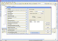
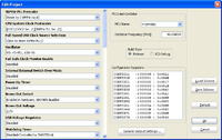
The Configuration Register settings can be found under the following menu:

Project -> Edit Project or Shift+Ctrl+E


BigDog
 
  • Like
Reactions: PA3040

    PA3040

    Points: 2
    Helpful Answer Positive Rating
Dear wp100 and bigdog
Thanks for reply

can you please advice me which voltages directly effect for above problem I shown in my first post. I mean vpp or vdd

thanks in advance
 

can you please advice me which voltages directly effect for above problem I shown in my first post. I mean vpp or vdd

I believe it could be either the Vdd or Vpp both require a stable and appropriate value.

How do you have the target circuit designed? Do you have an appropriate pullup resistor on MCLR?

I am not an expert on cloned PICkits, from personal experience I prefer foregoing the drama and just purchasing the genuine item.

BigDog
 
  • Like
Reactions: PA3040

    PA3040

    Points: 2
    Helpful Answer Positive Rating
Dear bogdog,
Thanks for reply

I used pullup resistor of 2.2k to MCLR
Thanks
 

Hi,

Are you programming in a dedicated programming socket or in a users circiut ?

For a dedicated programming socket you do not need any resistor, if its in circuit, ICSP, then you must us the components as specified in the PK2 user guide, section ICSP.
 
  • Like
Reactions: PA3040

    PA3040

    Points: 2
    Helpful Answer Positive Rating
I used pullup resistor of 2.2k to MCLR

Sound a bit low, I believe Microchip recommends a 10kΩ pullup resistor. You must remember there is virtually no current flow into MCLR and Vpp is significantly higher than the allowable Vdd, therefore some isolation of MCLR and the applied Vpp is typically needed.


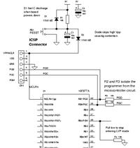
Although probably overkill, I typically use a ICSP port design similar to the following:


You may also want to try pulling PGM low, as in the above design, there have been reports that a floating PGM pin can be the source of programming issues.


BigDog
 
  • Like
Reactions: PA3040

    PA3040

    Points: 2
    Helpful Answer Positive Rating
Hi,

Just to follow on the point BDG makes about the Pics LVP pin, also ensure that in your program code the Configuration specifies LVP=OFF.
 

Just to follow on the point BDG makes about the Pics LVP pin, also ensure that in your program code the Configuration specifies LVP=OFF.

A valid point and often overlooked issue, thanks for bring it up.

BigDog
 

Dear bigdog/wp100,

Thanks you so much for reply
I never used in my cct PGM to ground via 10k resistor, I think this may be the problem
can you please advice, if I OFF LVP in config word, is it necessary to apply 10k resistor to PGM pin

Thanks in advance
 

....if I OFF LVP in config word, is it necessary to apply 10k resistor to PGM pin

I would suggest implementing both, after all it is not difficult add the pull down resistor.

At least you should be able to tell whether or not the PGM pin was the issue.

BigDog
 

Status
Not open for further replies.

Part and Inventory Search

Welcome to EDABoard.com

Sponsor

Back
Top